Quantcast
Channel: pic | Battery Guide
Viewing all 202 articles
Browse latest View live

Connect CAN-SPI with PIC Controller

$
0
0
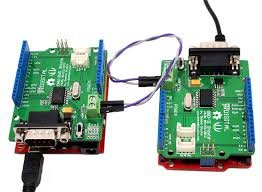
The SPI module is available with a number of the PIC compliant MCUs. The mikroC PRO for PIC provides a library (driver) for working with mikroElektronika’s CANSPI Add-on boards (with MCP2515 or MCP2510) via SPI interface.
The CAN is a very robust protocol that has error detection and signalization, self–checking and fault confinement. Faulty CAN data and remote frames are re-transmitted automatically, similar to the Ethernet.
In the mikroC PRO for PIC, each routine of the CAN library has its own CANSPI counterpart with identical syntax. For more information on Controller Area Network, consult the CAN Library. Note that an effective communication speed depends on SPI and certainly is slower than “real” CAN.
Data transfer rates depend on distance. For example, 1 Mbit/s can be achieved at network lengths below 40m while 250 Kbit/s can be achieved at network lengths below 250m. The greater distance the lower maximum bitrate that can be achieved. The lowest bitrate defined by the standard is 200Kbit/s. Cables used are shielded twisted pairs.
CAN supports two message formats:Connect CAN-SPI with PIC Controller
  • Standard format, with 11 identifier bits and
  • Extended format, with 29 identifier bits

  Important :

  • Consult the CAN standard about CAN bus termination resistance.
  • An effective CANSPI communication speed depends on SPI and certainly is slower than “real” CAN.
  • The library uses the SPI module for communication. User must initialize appropriate SPI module before using the CANSPI Library.
  • For MCUs with two SPI modules it is possible to initialize both of them and then switch by using the SPI_Set_Active routine.
  • CANSPI module refers to mikroElektronika’s CANSPI Add-on board connected to SPI module of MCU.

Library Dependency Tree

CANSPI Library Dependency Tree

External dependencies of CANSPI Library

The following variables must be defined in all projects using CANSPI Library: Description : Example :
extern sfr sbit CanSpi_CS; Chip Select line. sbit CanSpi_CS at RC0_bit;
extern sfr sbit CanSpi_Rst; Reset line. sbit CanSpi_Rst at RC2_bit;
extern sfr sbit CanSpi_CS_Direction; Direction of the Chip Select pin. sbit CanSpi_CS_Direction at TRISC0_bit;
extern sfr sbit CanSpi_Rst_Direction; Direction of the Reset pin. sbit CanSpi_Rst_Direction at TRISC2_bit;

Library Routines

  • CANSPISetOperationMode
  • CANSPIGetOperationMode
  • CANSPIInitialize
  • CANSPISetBaudRate
  • CANSPISetMask
  • CANSPISetFilter
  • CANSPIRead
  • CANSPIWrite

CANSPISetOperationMode

Prototype void CANSPISetOperationMode(char mode, char WAIT);
Returns Nothing.
Description Sets the CANSPI module to requested mode.
Parameters :
  • mode: CANSPI module operation mode. Valid values: CANSPI_OP_MODE constants.
  • WAIT: CANSPI mode switching verification request. If WAIT == 0, the call is non-blocking. The function does not verify if the CANSPI module is switched to requested mode or not. Caller must use CANSPIGetOperationMode to verify correct operation mode before performing mode specific operation. If WAIT != 0, the call is blocking – the function won’t “return” until the requested mode is set.
Requires The CANSPI routines are supported only by MCUs with the SPI module.
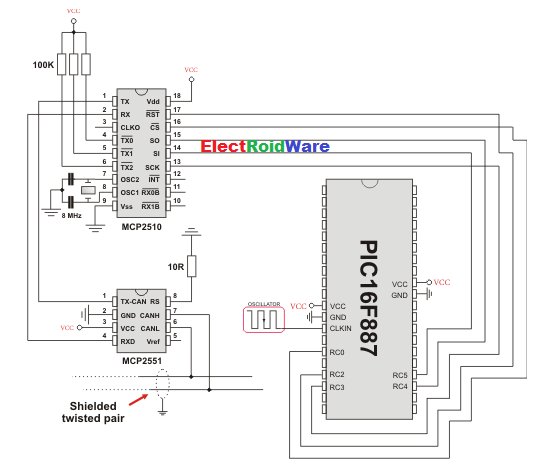
MCU has to be properly connected to mikroElektronika’s CANSPI Extra Board or similar hardware. See connection example at the bottom of this page.
Example
// set the CANSPI module into configuration mode (wait inside CANSPISetOperationMode until this mode is set)
CANSPISetOperationMode(_CANSPI_MODE_CONFIG, 0xFF);

CANSPIGetOperationMode

Prototype char CANSPIGetOperationMode();
Returns Current operation mode.
Description The function returns current operation mode of the CANSPI module. Check CANSPI_OP_MODE constants or device datasheet for operation mode codes.
Requires The CANSPI routines are supported only by MCUs with the SPI module.
MCU has to be properly connected to mikroElektronika’s CANSPI Extra Board or similar hardware. See connection example at the bottom of this page.
Example
// check whether the CANSPI module is in Normal mode and if it is do something.
if (CANSPIGetOperationMode() == _CANSPI_MODE_NORMAL) {
  ...
}

CANSPIInitialize

Prototype void CANSPIInitialize( char SJW, char BRP, char PHSEG1, char PHSEG2, char PROPSEG, char CANSPI_CONFIG_FLAGS);
Returns Nothing.
Description Initializes the CANSPI module.
Stand-Alone CAN controller in the CANSPI module is set to:
  • Disable CAN capture
  • Continue CAN operation in Idle mode
  • Do not abort pending transmissions
  • Fcan clock : 4*Tcy (Fosc)
  • Baud rate is set according to given parameters
  • CAN mode : Normal
  • Filter and mask registers IDs are set to zero
  • Filter and mask message frame type is set according to CANSPI_CONFIG_FLAGS value

SAM, SEG2PHTS, WAKFIL and DBEN bits are set according to CANSPI_CONFIG_FLAGS value.
Parameters:

  • SJW as defined in CAN controller’s datasheet
  • BRP as defined in CAN controller’s datasheet
  • PHSEG1 as defined in CAN controller’s datasheet
  • PHSEG2 as defined in CAN controller’s datasheet
  • PROPSEG as defined in CAN controller’s datasheet
  • CANSPI_CONFIG_FLAGS is formed from predefined constants
Requires Global variables :
  • CanSpi_CS: Chip Select line
  • CanSpi_Rst: Reset line
  • CanSpi_CS_Direction: Direction of the Chip Select pin
  • CanSpi_Rst_Direction: Direction of the Reset pin

must be defined before using this function.
The CANSPI routines are supported only by MCUs with the SPI module.
The SPI module needs to be initialized. See the SPIx_Init and SPIx_Init_Advanced routines.
MCU has to be properly connected to mikroElektronika’s CANSPI Extra Board or similar hardware. See connection example at the bottom of this page.

Example
// CANSPI module connections
sbit CanSpi_CS  at  RC0_bit;
sbit CanSpi_CS_Direction  at  TRISC0_bit;
sbit CanSpi_Rst at  RC2_bit;
sbit CanSpi_Rst_Direction at  TRISC2_bit;
// End CANSPI module connections

// initialize the CANSPI module with the appropriate baud rate and message acceptance flags along with the sampling rules
char CanSPi_Init_Flags;
  ...  
  CanSPi_Init_Flags = _CANSPI_CONFIG_SAMPLE_THRICE &  // form value to be used
                   _CANSPI_CONFIG_PHSEG2_PRG_ON &  // with CANSPIInitialize
                   _CANSPI_CONFIG_XTD_MSG &
                   _CANSPI_CONFIG_DBL_BUFFER_ON &
                   _CANSPI_CONFIG_VALID_XTD_MSG;
  ...
  SPI1_Init();                                // initialize SPI module
  CANSPIInitialize(1,3,3,3,1,CanSpi_Init_Flags);  // initialize external CANSPI module

CANSPISetBaudRate

Prototype void CANSPISetBaudRate( char SJW, char BRP, char PHSEG1, char PHSEG2, char PROPSEG, char CANSPI_CONFIG_FLAGS);
Returns Nothing.
Description Sets the CANSPI module baud rate. Due to complexity of the CAN protocol, you can not simply force a bps value. Instead, use this function when the CANSPI module is in Config mode.
SAM, SEG2PHTS and WAKFIL bits are set according to CANSPI_CONFIG_FLAGS value. Refer to datasheet for details.
Parameters:
  • SJW as defined in CAN controller’s datasheet
  • BRP as defined in CAN controller’s datasheet
  • PHSEG1 as defined in CAN controller’s datasheet
  • PHSEG2 as defined in CAN controller’s datasheet
  • PROPSEG as defined in CAN controller’s datasheet
  • CANSPI_CONFIG_FLAGS is formed from predefined constants
Requires The CANSPI module must be in Config mode, otherwise the function will be ignored.
The CANSPI routines are supported only by MCUs with the SPI module.
MCU has to be properly connected to mikroElektronika’s CANSPI Extra Board or similar hardware. See connection example at the bottom of this page.
Example
// set required baud rate and sampling rules
char canspi_config_flags;
...  
CANSPISetOperationMode(CANSPI_MODE_CONFIG,0xFF);              // set CONFIGURATION mode (CANSPI module mast be in config mode for baud rate settings)
canspi_config_flags = _CANSPI_CONFIG_SAMPLE_THRICE &
                   _CANSPI_CONFIG_PHSEG2_PRG_ON &
                   _CANSPI_CONFIG_STD_MSG       &
                   _CANSPI_CONFIG_DBL_BUFFER_ON &
                   _CANSPI_CONFIG_VALID_XTD_MSG &
                   _CANSPI_CONFIG_LINE_FILTER_OFF;
CANSPISetBaudRate(1, 1, 3, 3, 1, canspi_config_flags);

CANSPISetMask

Prototype void CANSPISetMask(char CANSPI_MASK, long val, char CANSPI_CONFIG_FLAGS);
Returns Nothing.
Description Configures mask for advanced filtering of messages. The parameter value is bit-adjusted to the appropriate mask registers.
Parameters:
  • CANSPI_MASK: CANSPI module mask number. Valid values: CANSPI_MASK constants (see CANSPI constants)
  • val: mask register value
  • CANSPI_CONFIG_FLAGS: selects type of message to filter. Valid values:
    • _CANSPI_CONFIG_ALL_VALID_MSG,
    • _CANSPI_CONFIG_MATCH_MSG_TYPE & _CANSPI_CONFIG_STD_MSG,
    • _CANSPI_CONFIG_MATCH_MSG_TYPE & _CANSPI_CONFIG_XTD_MSG.
Requires The CANSPI module must be in Config mode, otherwise the function will be ignored. See CANSPISetOperationMode.
The CANSPI routines are supported only by MCUs with the SPI module.
MCU has to be properly connected to mikroElektronika’s CANSPI Extra Board or similar hardware. See connection example at the bottom of this page.
Example
// set the appropriate filter mask and message type value
CANSPISetOperationMode(_CANSPI_MODE_CONFIG,0xFF);              // set CONFIGURATION mode (CANSPI module must be in config mode for mask settings)

// Set all B1 mask bits to 1 (all filtered bits are relevant):
// Note that -1 is just a cheaper way to write 0xFFFFFFFF.
// Complement will do the trick and fill it up with ones.
CANSPISetMask(_CANSPI_MASK_B1, -1, _CANSPI_CONFIG_MATCH_MSG_TYPE & _CANSPI_CONFIG_XTD_MSG);

CANSPISetFilter

Prototype void CANSPISetFilter(char CANSPI_FILTER, long val, char CANSPI_CONFIG_FLAGS);
Returns Nothing.
Description Configures message filter. The parameter value is bit-adjusted to the appropriate filter registers.
Parameters:
  • CANSPI_FILTER: CANSPI module filter number. Valid values: CANSPI_FILTER constants
  • val: filter register value
  • CANSPI_CONFIG_FLAGS: selects type of message to filter. Valid values:
    • _CANSPI_CONFIG_ALL_VALID_MSG,
    • _CANSPI_CONFIG_MATCH_MSG_TYPE & _CANSPI_CONFIG_STD_MSG,
    • _CANSPI_CONFIG_MATCH_MSG_TYPE & _CANSPI_CONFIG_XTD_MSG.
Requires The CANSPI module must be in Config mode, otherwise the function will be ignored.
The CANSPI routines are supported only by MCUs with the SPI module.
MCU has to be properly connected to mikroElektronika’s CANSPI Extra Board or similar hardware. See connection example at the bottom of this page.
Example
// set the appropriate filter value and message type
CANSPISetOperationMode(_CANSPI_MODE_CONFIG,0xFF);                  // set CONFIGURATION mode (CANSPI module must be in config mode for filter settings)

/* Set id of filter B1_F1 to 3: */
CANSPISetFilter(_CANSPI_FILTER_B1_F1, 3, _CANSPI_CONFIG_XTD_MSG);

CANSPIRead

Prototype char CANSPIRead(long *id, char *rd_data, char *data_len, char *CANSPI_RX_MSG_FLAGS);
Returns
  • 0 if nothing is received
  • 0xFF if one of the Receive Buffers is full (message received)
Description If at least one full Receive Buffer is found, it will be processed in the following way:
  • Message ID is retrieved and stored to location provided by the id parameter
  • Message data is retrieved and stored to a buffer provided by the rd_data parameter
  • Message length is retrieved and stored to location provided by the data_len parameter
  • Message flags are retrieved and stored to location provided by the CANSPI_RX_MSG_FLAGS parameter

Parameters:

  • id: message identifier storage address
  • rd_data: data buffer (an array of bytes up to 8 bytes in length)
  • data_len: data length storage address.
  • CANSPI_RX_MSG_FLAGS: message flags storage address
Requires The CANSPI module must be in a mode in which receiving is possible.
The CANSPI routines are supported only by MCUs with the SPI module.
MCU has to be properly connected to mikroElektronika’s CANSPI Extra Board or similar hardware. See connection example at the bottom of this page.
Example
// check the CANSPI module for received messages. If any was received do something. 
char msg_rcvd, rx_flags, data_len;
char data[8];
long msg_id;
...
CANSPISetOperationMode(_CANSPI_MODE_NORMAL,0xFF);                  // set NORMAL mode (CANSPI module must be in mode in which receive is possible)
...
rx_flags = 0;                                                // clear message flags
if (msg_rcvd = CANSPIRead(msg_id, data, data_len, rx_flags)) {
  ...
}

Connect CAN-SPI with PIC Controller schematichCANSPIWrite

Prototype char CANSPIWrite(long id, char *wr_data, char data_len, char CANSPI_TX_MSG_FLAGS);
Returns
  • 0 if all Transmit Buffers are busy
  • 0xFF if at least one Transmit Buffer is available
Description If at least one empty Transmit Buffer is found, the function sends message in the queue for transmission.
Parameters:
  • id:CAN message identifier. Valid values: 11 or 29 bit values, depending on message type (standard or extended)
  • wr_data: data to be sent (an array of bytes up to 8 bytes in length)
  • data_len: data length. Valid values: 1 to 8
  • CANSPI_RX_MSG_FLAGS: message flags
Requires The CANSPI module must be in mode in which transmission is possible.
The CANSPI routines are supported only by MCUs with the SPI module.
MCU has to be properly connected to mikroElektronika’s CANSPI Extra Board or similar hardware. See connection example at the bottom of this page.
Example
// send message extended CAN message with the appropriate ID and data
char tx_flags;
char data[8];
long msg_id;
...
CANSPISetOperationMode(_CANSPI_MODE_NORMAL,0xFF);                  // set NORMAL mode (CANSPI must be in mode in which transmission is possible)

tx_flags = _CANSPI_TX_PRIORITY_0 & _CANSPI_TX_XTD_FRAME;             // set message flags
CANSPIWrite(msg_id, data, 2, tx_flags);


For more detail: Connect CAN-SPI with PIC Controller

The post Connect CAN-SPI with PIC Controller appeared first on PIC Microcontroller.

Connect CAN Protocol with PIC

$
0
0
The mikroC PRO for PIC provides a library (driver) for working with the CAN module.
The CAN is a very robust protocol that has error detection and signalization, self–checking and fault confinement. Faulty CAN data and remote frames are re-transmitted automatically, similar to the Ethernet.
Data transfer rates depends on the distance. For example, 1 Mbit/s can be achieved at network lengths below 40m while 250 Kbit/s can be achieved at network lengths below 250m. The greater distance the lower maximum bitrate that can be achieved. The lowest bitrate defined by the standard is 200Kbit/s. Cables used are shielded twisted pairs.
CAN supports two message formats:
  • Standard format, with 11 identifier bits, and
  • Extended format, with 29 identifier bits
  Important :
  • Consult the CAN standard about CAN bus termination resistance.


Library Routines

  • CANSetOperationMode
  • CANGetOperationMode
  • CANInitialize
  • CANSetBaudRate
  • CANSetMask
  • CANSetFilter
  • CANRead
  • CANWrite
  • CANSetTxIdleLevelConnect CAN Protocol with PIC

CANSetOperationMode

Prototype void CANSetOperationMode(unsigned short mode, unsigned short wait_flag);
Returns Nothing.
Description Sets CAN to requested mode, i.e. copies mode to CANSTAT. Parameter mode needs to be one of CAN_OP_MODE constants .
Parameter wait_flag needs to be either 0 or 0xFF:
  • If set to 0xFF, this is a blocking call – the function won’t “return” until the requested mode is set.
  • If 0, this is a non-blocking call. It does not verify if CAN module is switched to requested mode or not. Caller must use CANGetOperationMode to verify correct operation mode before performing mode specific operation.
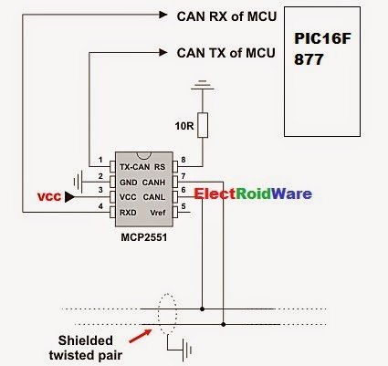
Requires Microcontroller must be connected to CAN transceiver (MCP2551 or similar) which is connected to CAN bus.
Example
CANSetOperationMode(_CAN_MODE_CONFIG, 0xFF);

CANGetOperationMode

Prototype unsigned short CANGetOperationMode();
Returns Current opmode.
Description Function returns current operational mode of CAN module.
Requires Microcontroller must be connected to CAN transceiver (MCP2551 or similar) which is connected to CAN bus.
Example
if (CANGetOperationMode() == _CAN_MODE_NORMAL) { ... };

CANInitialize

Prototype void CANInitialize(char SJW, char BRP, char PHSEG1, char PHSEG2, char PROPSEG, char CAN_CONFIG_FLAGS);
Returns Nothing.
Description Initializes CAN. All pending transmissions are aborted. Sets all mask registers to 0 to allow all messages.
Filter registers are set according to flag value:
if (CAN_CONFIG_FLAGS & _CAN_CONFIG_VALID_XTD_MSG != 0)
  // Set all filters to XTD_MSG
else if (config & _CAN_CONFIG_VALID_STD_MSG != 0)
  // Set all filters to STD_MSG
else
  // Set half of the filters to STD, and the rest to XTD_MSG.

Parameters:

  • SJW as defined in datasheet (1–4)
  • BRP as defined in datasheet (1–64)
  • PHSEG1 as defined in datasheet (1–8)
  • PHSEG2 as defined in datasheet (1–8)
  • PROPSEG as defined in datasheet (1–8)
  • CAN_CONFIG_FLAGS is formed from predefined constants
Requires CAN must be in Config mode; otherwise the function will be ignored.
Microcontroller must be connected to CAN transceiver (MCP2551 or similar) which is connected to CAN bus.
Example
init = _CAN_CONFIG_SAMPLE_THRICE &
       _CAN_CONFIG_PHSEG2_PRG_ON &
       _CAN_CONFIG_STD_MSG       &
       _CAN_CONFIG_DBL_BUFFER_ON &
       _CAN_CONFIG_VALID_XTD_MSG &
       _CAN_CONFIG_LINE_FILTER_OFF;
...
CANInitialize(1, 1, 3, 3, 1, init);   // initialize CAN

CANSetBaudRate

Prototype void CANSetBaudRate(char SJW, char BRP, char PHSEG1, char PHSEG2, char PROPSEG, char CAN_CONFIG_FLAGS);
Returns Nothing.
Description Sets CAN baud rate. Due to complexity of CAN protocol, you cannot simply force a bps value. Instead, use this function when CAN is in Config mode. Refer to datasheet for details.
Parameters:
  • SJW as defined in datasheet (1–4)
  • BRP as defined in datasheet (1–64)
  • PHSEG1 as defined in datasheet (1–8)
  • PHSEG2 as defined in datasheet (1–8)
  • PROPSEG as defined in datasheet (1–8)
  • CAN_CONFIG_FLAGS is formed from predefined constants
Requires CAN must be in Config mode; otherwise the function will be ignored.
Microcontroller must be connected to CAN transceiver (MCP2551 or similar) which is connected to CAN bus.
Example
init = _CAN_CONFIG_SAMPLE_THRICE &
       _CAN_CONFIG_PHSEG2_PRG_ON &
       _CAN_CONFIG_STD_MSG       &
       _CAN_CONFIG_DBL_BUFFER_ON &
       _CAN_CONFIG_VALID_XTD_MSG &
       _CAN_CONFIG_LINE_FILTER_OFF;
...
CANSetBaudRate(1, 1, 3, 3, 1, init);

CANSetMask

Prototype void CANSetMask(char CAN_MASK, long value, char CAN_CONFIG_FLAGS);
Returns Nothing.
Description Function sets mask for advanced filtering of messages. Given value is bit adjusted to appropriate buffer mask registers.
Parameters:
  • CAN_MASK is one of predefined constant values
  • value is the mask register value
  • CAN_CONFIG_FLAGS selects type of message to filter, either _CAN_CONFIG_XTD_MSG or _CAN_CONFIG_STD_MSG
Requires CAN must be in Config mode; otherwise the function will be ignored.
Microcontroller must be connected to CAN transceiver (MCP2551 or similar) which is connected to CAN bus.
Example
// Set all mask bits to 1, i.e. all filtered bits are relevant:
CANSetMask(_CAN_MASK_B1, -1, _CAN_CONFIG_XTD_MSG);

// Note that -1 is just a cheaper way to write 0xFFFFFFFF.
   Complement will do the trick and fill it up with ones.

CANSetFilter

Prototype void CANSetFilter(char CAN_FILTER, long value, char CAN_CONFIG_FLAGS);
Returns Nothing.
Description Function sets message filter. Given value is bit adjusted to appropriate buffer mask registers.
Parameters:
  • CAN_FILTER is one of predefined constant values
  • value is the filter register value
  • CAN_CONFIG_FLAGS selects type of message to filter, either _CAN_CONFIG_XTD_MSG or _CAN_CONFIG_STD_MSG
Requires CAN must be in Config mode; otherwise the function will be ignored.
Microcontroller must be connected to CAN transceiver (MCP2551 or similar) which is connected to CAN bus.
Example
// Set id of filter B1_F1 to 3:
CANSetFilter(_CAN_FILTER_B1_F1, 3, _CAN_CONFIG_XTD_MSG);

CANRead

Prototype char CANRead(long *id, char *data, char *datalen, char *CAN_RX_MSG_FLAGS);
Returns Message from receive buffer or zero if no message found.
Description Function reads message from receive buffer. If at least one full receive buffer is found, it is extracted and returned. If none found, function returns zero.
Parameters:
  • id is message identifier
  • data is an array of bytes up to 8 bytes in length
  • datalen is data length, from 1–8.
  • CAN_RX_MSG_FLAGS is value formed from constants
Requires CAN must be in mode in which receiving is possible.
Microcontroller must be connected to CAN transceiver (MCP2551 or similar) which is connected to CAN bus.
Example
char rcv, rx, len, data[8];
long id;

// ...
rx = 0;
// ...
rcv = CANRead(id, data, len, rx);

CANWrite

Prototype unsigned short CANWrite(long id, char *data, char datalen, char CAN_TX_MSG_FLAGS);
Returns Returns zero if message cannot be queued (buffer full).
Description If at least one empty transmit buffer is found, function sends message on queue for transmission. If buffer is full, function returns 0.
Parameters:
  • id is CAN message identifier. Only 11 or 29 bits may be used depending on message type (standard or extended)
  • data is array of bytes up to 8 bytes in length
  • datalen is data length from 1–8
  • CAN_TX_MSG_FLAGS is value formed from constants
Requires CAN must be in Normal mode.
Microcontroller must be connected to CAN transceiver (MCP2551 or similar) which is connected to CAN bus.
Example
char tx, data;
long id;

// ...
tx = _CAN_TX_PRIORITY_0 &
     _CAN_TX_XTD_FRAME;
// ...
CANWrite(id, data, 2, tx);

CANSetTxIdleLevel

Prototype void CANSetTxIdleLevel(char driveHighState);
Returns Nothing.
Description This function sets the state of CANTX pin when recessive.
Parameters:
  • driveHighState: State of the CANTX pin. Valid values :
    Description Predefined library const
    CANTX pin will drive VDD when recessive.
    Use it when using a differential bus to avoid signal crosstalk in CANTX from other nearby pins.
    _CAN_DRIVE_HIGH_STATE_ENABLE
    CANTX pin will be tri-state when recessive. _CAN_DRIVE_HIGH_STATE_DISABLE
Requires Microcontroller must be connected to CAN transceiver (MCP2551 or similar) which is connected to CAN bus.
Example
CANSetTxIdleLevel(_CAN_DRIVE_HIGH_STATE_ENABLE);

CAN Constants

There is a number of constants predefined in CAN library. To be able to use the library effectively, you need to be familiar with these. You might want to check the example at the end of the chapter.

CAN_OP_MODE

CAN_OP_MODE constants define CAN operation mode. Function CANSetOperationMode expects one of these as its argument:
const char
_CAN_MODE_BITS = 0xE0, // Use this to access opmode bits
_CAN_MODE_NORMAL = 0x00,
    _CAN_MODE_SLEEP  = 0x20,
_CAN_MODE_LISTEN = 0x60,
    _CAN_MODE_LOOP   = 0x40,
Connect CAN Protocol with PIC schematich_CAN_MODE_CONFIG = 0x80;
CAN_CONFIG_FLAGS
CAN_CONFIG_FLAGS constants define flags related to CAN module configuration. Functions CANInitialize and CANSetBaudRate expect one of these (or a bitwise combination) as their argument:
const char
_CAN_CONFIG_DEFAULT = 0xFF, // 11111111
_CAN_CONFIG_PHSEG2_PRG_BIT = 0x01,
_CAN_CONFIG_PHSEG2_PRG_ON = 0xFF, // XXXXXXX1
_CAN_CONFIG_PHSEG2_PRG_OFF = 0xFE, // XXXXXXX0
_CAN_CONFIG_LINE_FILTER_BIT = 0x02,
_CAN_CONFIG_LINE_FILTER_ON = 0xFF, // XXXXXX1X
_CAN_CONFIG_LINE_FILTER_OFF = 0xFD, // XXXXXX0X
_CAN_CONFIG_SAMPLE_BIT = 0x04,
_CAN_CONFIG_SAMPLE_ONCE = 0xFF, // XXXXX1XX
_CAN_CONFIG_SAMPLE_THRICE = 0xFB, // XXXXX0XX
_CAN_CONFIG_MSG_TYPE_BIT = 0x08,
_CAN_CONFIG_STD_MSG = 0xFF, // XXXX1XXX
_CAN_CONFIG_XTD_MSG = 0xF7, // XXXX0XXX
_CAN_CONFIG_DBL_BUFFER_BIT = 0x10,
_CAN_CONFIG_DBL_BUFFER_ON = 0xFF, // XXX1XXXX
_CAN_CONFIG_DBL_BUFFER_OFF = 0xEF, // XXX0XXXX
_CAN_CONFIG_MSG_BITS = 0x60,
_CAN_CONFIG_ALL_MSG = 0xFF, // X11XXXXX
_CAN_CONFIG_VALID_XTD_MSG = 0xDF, // X10XXXXX
_CAN_CONFIG_VALID_STD_MSG = 0xBF, // X01XXXXX
_CAN_CONFIG_ALL_VALID_MSG = 0x9F; // X00XXXXX
You may use bitwise AND (&) to form config byte out of these values. For example:
init = _CAN_CONFIG_SAMPLE_THRICE &
       _CAN_CONFIG_PHSEG2_PRG_ON &
_CAN_CONFIG_DBL_BUFFER_ON &
_CAN_CONFIG_STD_MSG       &
       _CAN_CONFIG_VALID_XTD_MSG &


For more detail: Connect CAN Protocol with PIC

The post Connect CAN Protocol with PIC appeared first on PIC Microcontroller.
Microchip PIC Programmer ICSP Circuit Requirements

$
0
0

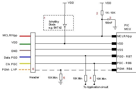
Microchip do not recommend any particular circuit for ICSP programming. There are diagrams for different tools, such as Pro Mate and PICKit2 with similar circuitry but slight variations. In some schematics, their suggested resistor values are too small, in our opinion, and can cause problems with programmers, even Microchip ones.

Microchip PIC Programmer ICSP Circuit

Kanda have developed a recommended In System Programming circuit that will work effectively with our PIC programmer range, and other PIC programmers. This circuit is shown in the diagram below. Please read the notes that describe the circuit and explain the effect of extra components such as capacitors. Microchip PIC Programmer ICSP Circuit Requirements

Notes on PIC ICSP Circuit
  1. Kanda programmers are designed to provide 3.3V or 5V to the target circuit, but some other ICSP programmers always supply 5V. If your circuit operates at a lower voltage than the programmer, then the diode shown on VDD should be fitted to protect the rest of the circuit. A series resistor may be acceptable instead of the diode in some cases.
    The maximum current that the programmer can supply is often limited, so you should fit the diode on VDD if the programmer over-current circuit trips.
  2. MCLR/VPP pin needs a resistor to VDD. A minimum of 1K should work but 10K is better. PIC16F devices with only VDD first ICSP entry (PIC16F8x/87x/7x/7×7) should be fitted with a 4K7 resistor as a minimum to reduce the possibility of code running before VPP rises. Supervisory circuits or push buttons on MCLR should be isolated from the VPP voltage, by placing them on the VDD side of the resistor or by fitting a Schottky diode on this line as per note 1.
  3. The 100nF capacitor shown on MCLR/VPP pin is optional for HVP but we do recommend that a capacitor is fitted to avoid glitches on MCLR. 100nF is the maximum value, and we recommend something smaller. Larger capacitors may prevent the PIC from entering HVP mode. Do not fit for LVP mode.
  4. If possible, Clock and Data lines should be dedicated to ICSP but where this is not possible, the application circuit should be isolated from the data and clock lines with series resistors, above 10K. This is especially important if either of these lines forces the pin as an input or output. In exceptional cases, series resistors may not be sufficient and a 4053 multiplexer or similar circuit should be used.
    Capacitors on these programming lines should be avoided if at all possible. If they are needed, for noise immunity for example, then the maximum capacitance that all programmers can handle is 1nF, although some are better.
  5. If LVP mode is used, this resistor must be fitted.
  6. The PGM line is only needed for Low Voltage Programming – LVP mode.
  7. PIC18F J parts need a decoupling capacitor between VccCore pin and Ground, typically 100nF.
Notes on PIC ICSP Circuit
  1. Kanda programmers are designed to provide 3.3V or 5V to the target circuit, but some other ICSP programmers always supply 5V. If your circuit operates at a lower voltage than the programmer, then the diode shown on VDD should be fitted to protect the rest of the circuit. A series resistor may be acceptable instead of the diode in some cases.
    The maximum current that the programmer can supply is often limited, so you should fit the diode on VDD if the programmer over-current circuit trips.
  2. MCLR/VPP pin needs a resistor to VDD. A minimum of 1K should work but 10K is better. PIC16F devices with only VDD first ICSP entry (PIC16F8x/87x/7x/7×7) should be fitted with a 4K7 resistor as a minimum to reduce the possibility of code running before VPP rises. Supervisory circuits or push buttons on MCLR should be isolated from the VPP voltage, by placing them on the VDD side of the resistor or by fitting a Schottky diode on this line as per note 1.
  3. The 100nF capacitor shown on MCLR/VPP pin is optional for HVP but we do recommend that a capacitor is fitted to avoid glitches on MCLR. 100nF is the maximum value, and we recommend something smaller. Larger capacitors may prevent the PIC from entering HVP mode. Do not fit for LVP mode.
  4. If possible, Clock and Data lines should be dedicated to ICSP but where this is not possible, the application circuit should be isolated from the data and clock lines with series resistors, above 10K. This is especially important if either of these lines forces the pin as an input or output. In exceptional cases, series resistors may not be sufficient and a 4053 multiplexer or similar circuit should be used.
    Capacitors on these programming lines should be avoided if at all possible. If they are needed, for noise immunity for example, then the maximum capacitance that all programmers can handle is 1nF, although some are better.
  5. If LVP mode is used, this resistor must be fitted.
  6. The PGM line is only needed for Low Voltage Programming – LVP mode.
  7. PIC18F J parts need a decoupling capacitor between VccCore pin and Ground, typically 100nF.Microchip PIC Programmer ICSP Circuit Requirements schematich

Kanda ICSP PIC Programmers

Kanda ICSP PIC ProgrammersKanda Handheld PIC Programmers will provide 3.3V or 5V VDD to target PIC microcontroller circuits. The target circuit can be powered or unpowered. This can be user selected for most PIC microcontrollers but it is fixed to 3.3V for J type PIC microcontrollers and LF parts that can be damaged by 5V. The high Voltage programming voltage (VPP) is set to 12V for most PIC devices but is automatically set to 9V for PIC18F K type and newest PIC16F PIC microcontrollers


For more detail: Microchip PIC Programmer ICSP Circuit Requirements

The post Microchip PIC Programmer ICSP Circuit Requirements appeared first on PIC Microcontroller.
Connect to the PIC Microcontroller

$
0
0

A Simple Development Board

Ok, so you have now got your programmer, and you have a PIC or two. It is all very well knowing how to program the PIC in theory, but the real learning comes when you try your code on a PIC and see the results yourself in a circuit.

You could build a circuit each time and program the PIC to see if the program works, or you can make yourself a development board.Connect to the PIC Microcontroller A development board allows you to simulate the environment around the PIC. We have included a circuit diagram to show a very basic and cheap development board. You can, of course add LEDs and switches to this, but We have included the bare bones. You can monitor the Input/Output pins by connecting LEDs directly to the pins, and they will light up when the pins go high. Also, you can add switches to the pins, so that you can select which inputs are high, and which are low. Basically, what We are saying is if you start with this circuit, you can add whatever you feel necessary.

We will run through the circuit diagram, which We admit isn’t much, but it will give you a feel of things to come.

The supply rail is set to +6V, which is the maximum voltage of the PIC. You can use any voltage below this right down to +2V. C3 is known as a ‘Bypass’ Capacitor. All C3 does is reduce any noise on the supply rail. X1 is a 4MHz crystal. You could use a parallel resistor and capacitor circuit, but the cost of the crystal is negligible, and it is more stable.Connect to the PIC Microcontroller C1 and C2 help reduce any stray oscillations across the crystal, and get rid of any unwanted noise etc before the signal goes into the PIC.

Note: To report broken links or to submit your projects please send email toWebmaster


For more detail: Connect to the PIC Microcontroller

The post Connect to the PIC Microcontroller appeared first on PIC Microcontroller.
PIC Frequency Counter with Frequency Lock function

$
0
0

Table of Content:
Frequency Reference
Frequency Actual
Subtraction and Comparator
Digital Outputs
Integrator
Transistors Q2…Q4
Connection to Oscillator
How to tune?
PIC SW in the frequency counter
Final test
RB2 Function
Is this worth to build it?

PIC Frequency Counter with Frequency Lock functionPictures are better readable locally with appropriate viewer, so we suggest download them first

This PIC software combines frequency counter and frequency lock functions. By adding couple of transistors and operation amplifier TL082, it is possible to lock the LC oscillator frequency.

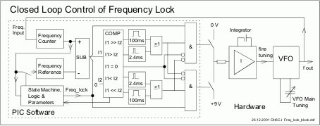
Let’s look at the following block diagram. Software functions are presented inside the dashed area.

Frequency Reference

Frequency reference is formed from the measured frequency itself after the delay defined by parameter 0Dh, when the number of the consecutive samples (defined by 0Eh) of measured frequency are within the +/-20 Hz. Then the actual value is trigged as frequency reference until the SW detects that the lock conditions are not valid.

Frequency Actual

Frequency actual is formed from the frequency counter function itself.

Subtraction and Comparator

Frequency is measured every 100 ms. Next the frequency actual is subtracted from the reference and the difference is compared to value zero to calculate the deviation. If the result is zero, it means that no deviation and also no need to fine-tune the oscillator frequency.

If the result is negative it means that the frequency actual is higher than reference. This detects the direction of the needed frequency correction. Next the rough value of the difference is calculated. If within 20 Hz then only short 2.4 ms pulse is controlled. If bigger then 100 ms pulse is controlled. By means of these few calculations we have information how to fine-tune the frequency of the oscillator to hold the frequency actual equal as frequency reference. Simple, is it?

Digital Outputs

These pulses are controlled to digital outputs RB0 or RB3 according to the sign of the frequency difference. The outputs are never simultaneously on because it means almost short circuit.

Integrator

The controller is made using TL082 operation amplifier. The first amplifier is an integrator by means of the capacitor C8 and R23. A time constant is R23 * C8 = 22 M Ohms * 2.2 uF = 48 s. So the control is slow and it only fine tunes the oscillator frequency and this is of course the purpose of the controller. The VFO itself must be stable enough. Second amplifier of TL082 is connected as a buffer.PIC Frequency Counter with Frequency Lock function schematich

Transistors Q2…Q4

If the PIC SW controls the output RB0 to state TRUE, then led D4 is light and Q2 saturates. It connects integrator input via R23 to GND and the voltage at the output pin 1 changes to positive direction. If the RB3 is controlled to state TRUE, D4 is light and Q3 connects the base of the Q4 to ground. As a result Q4 is saturated and +9 V is connected to the R23. Now output changes to negative direction. If none of RBs are controlled, the integrator acts an analogue memory. It holds the last value at the output. This suites well for the situation where the subtraction result of reference and actual is zero. The used transistor types are not critical.


For more detail: PIC Frequency Counter with Frequency Lock function

The post PIC Frequency Counter with Frequency Lock function appeared first on PIC Microcontroller.
Computer controlled infrared transmitter based on PIC

$
0
0

description

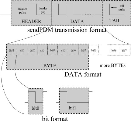
This is a programmable infrared (remote control) transmitter, which can be controlled from a computer serial port. It is capable of sending many remote control formats, including the Philips RC-5 standard. Exact formats with the timing parameter names are shown on the pictures:

operation

The controller will accept commands on a serial port. Settings are: 19200 bps, 8 bits, no parity, 1 stopbit, no flow control (XON/XOFF or RTS/CTS). Commands consist of hex coded bytes and must be written on the port as ASCII characters separated by space, terminated by ENTER (ASCII char 0x0d). The list of commands is here:Computer controlled infrared transmitter based on PIC

command parameters and description
SETSTATE set IR mod output state
Setting the mod output HIGH for a long time can result in blowing the IR transmitter LED out!
54 <state>
SETPARAMS set coding parameters (first format for SENDPDM, second for SENDRC5)
55 <ir_T> <head_h> <head_l> <bit0_h> <bit0_l> <bit1_h> <bit1_l> <tail_h> <tail_l>
55 <ir_T> <skipbits> <togglebits> <firstbyte> <rc5tail>
SETPWM set PWM parameters
modify PWM modulation. PWM period time = pwm_T * 1 usecs, PWM duty cycle = dc_T * 0.25 usecs
58 <pwm_T> <dc_T>
SENDPDM send ir command
header pulse high for T*head_h, low for T*head_l (see transmission format, picture)
data bytes transmitted as: bit#0 bit#1 bit#2 bit#3 bit#4 bit#5 bit#6 bit#7 (see DATA format, picture)
tail bit is high for T*tail_h, bit0 is high for T*bit0_h, low for T*bit0_1,bit1 is high for T*bit1_h, low for T*bit1_l
56 <byte> [byte] [byte] …
SENDRC5 send ir command
transmit (16-skipbits) bits: lower (8-skipbits) bits from <firstbyte> then 8 bits from <secondbyte>. The first byte is defined in the SETPARAMS command, second byte is given as parameter
data bytes are transmitted as: bit#7 bit#6 bit#5 bit#4 bit#3 bit#2 bit#1 bit#0
bit0 is high for T, low for T, bit1 is low for T, high for T (see transmission format, picture)
The bit(s) of <firstbyte> defined in <togglebits> are toggled after the completition of this command.Each <secondbyte> parameter given in this command will transmit a count of (16-skipbits) bits, without updating the toggle bit. The recommended use is to give the same <secondbyte> parameter multiple times to repeat the same code. This is the behaviour when a remote control button is held. The toggle bit is only updated when the command is finished. To send multiple IR codes, issue multiple SENDRC5 commands.
57 <second byte> [second byte] …

ir_T is given in 10 usecs, all other timing values are given in ir_T steps

You can use a terminal emulator program to test out the circuit (for example minicom on linux, NC terminal on DOS, or hyperterminal on windows). Line editing is not supported, only the backspace key works.

source code

Download source code and the HEX file here. The default modulation frequency is defined in the source: pwm_freq EQU d'36000' – adjust it as required. The default PWM duty cycle is 50%.

examples

line sent explanation
55 38 10 8 1 1 1 3 1 1 SETPARAMS ir_T=0x38=56d head_H=0x10=16d head_L=8 bit0_H=1 bit0_L=1 bit1_H=1 bit1_L=3 tail_H=1 tail_L=1
This command will set these PDM parameters: T=56*10=560 usec, header pulse=16T, header gap=8T. bit0 pulse=1T, bit0 gap=1T, bit1 pulse=1T, bit1 gap=3T, tail pulse=1T
56 31 ce 01 fe SENDPDM 0x31 0xce 0x01 0xfe
This command will transmit a header, 32 data bits given as parameter and a tail pulse as seen:

Computer controlled infrared transmitter based on PIC schematic

55 59 2 8 f8 65 SETPARAMS ir_T=0x59=89d skipbits=2 togglebits=8 firstbyte=0xf8 rc5tail=0x65=101d
This command will set these RC5 parameters: T=89*10=890 usec, skipbits=2 (16-2=14 bits IR code sent), firstbyte=0xf8, tail gap=101T=89.89 msec
58 1c 1c SETPWM pwm_T=0x1c=28d dc_T=0x1c=28d
This command will set PWM modulation to period time = 28 usecs (f = 35714 Hz), duty cycle = 28 * 0.25 usecs = 7 usecs = 25%
57 c SENDRC5 0x0c
This command will transmit a total of (16-skipbits)=14 bits. The first 6 bits are from firstbyte bit#5-#0: 1 1 0 0 0 0. Second 8 bits are <secondbyte>=0x0c: 0 0 0 0 1 1 0 0


57 c SENDRC5 0x0c
Repeating a SENDRC5 command will transmit an IR command with the toggle bit(s) updated. bit#3 from firstbyte is toggled from 0 to 1: 1 1 1 0 0 0. Second 8 bits: 0 0 0 0 1 1 0 0


For more detail: Computer controlled infrared transmitter based on PIC

The post Computer controlled infrared transmitter based on PIC appeared first on PIC Microcontroller.
High res cap meter with PIC 16F628

$
0
0

High resolution capacitance meter measures in 0.01pF digits. Total range 0pF to 50uF. – 27th Jun 2011, Updated 25th may 2013.

Another PIC based capacitance meter?
Although there are a few PIC based “pico” capacitance meters on the internet this design has some advantages over the other designs I have seen;

1. It has very high resolution; from 6 to 7 digits! (Others have 3 or 4 digits)
2. It has a wide range; 0pF to 50uF. (Others do not go over 0.1uF or 1uF)
3. It uses only a single cheap PIC 16F628. (Others use two ICs)
4. It does not need calibration! (Others need calibrating with a special test cap)
5. It can do auto-zeroing, floating zero and negative capacitance (relative to zero). High res cap meter with PIC 16F628
How it works
For absolute simplicity I used a PIC16F628. The oscillator uses the PICs internal comparator so no second IC is needed.

The oscillator is an RC comparator oscillator that switches between 1/3 Vdd and 2/3 Vdd, this is a proven system and the frequency is reasonably unaffected by small changes in the 5v Vdd.

The three 1k5 resistors (green) set the threshold voltages at 1/3Vdd and 2/3Vdd when the comparator output switches. (The PIC is a better comparator than many dedicated comaprator ICs as its output has good push-pull low-Rds FETs).

The oscillation period (freq) is set entirely by RT and CT. RT is a 1% metal film resistor which I measured on my multimeter at 10.00 kohm. Now the only thing that sets the oscillation period is the test cap CT.

The final stage is the PIC timer, that measures the oscillation period very precisely compared to the PICs xtal. And a math calc is done to scale the period to capacitance in farads.

Precision period measuring!

The PIC measures the RC oscillation period by using the PIC’s internal hardware capture (CCP1). The PIC xtal is 16MHz so the PIC timer runs at 4MHz.

It adds consecutive captured periods until there is a total accumulated time greater than 2 million counts (>0.5 second). The only error can be the edge error for the first and last capture, so the error is limited to 1 part in 2 million at each end, a total possible error of 1 PPM (1 Part Per Million).

Now it has a precise captured total of periods the average period is determined by dividing the total period with the number of periods captured. As the total is always just over 2 million it is scaled up to 2 billion before the division, to give a lot of accurate decimal digits after the division.

For example;
“10nF” cap, oscillates about 435Hz
218 consecutive periods are captured, a total of 2004597 counts
Math; (2004597*1000)/218 = 2004597000/218 = 9195399
(so the average period is 9195.399 counts)

A second process is used to convert that result to picofarads;
(9195399*100)/scale = 919539900/919 = 1000587
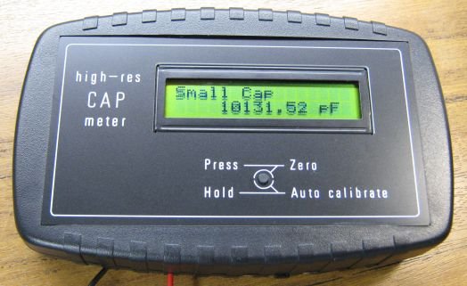
1000587 is then displayed as; 10005.87 pF

Another small cap example;
“100pF” osc about 43500 Hz
21751 periods are captured, a total of 2000091 counts
Math; 2000091000/21751 = 91953
 Scaling; 91953000/919 = 100057
100057 is truncated and displayed as 100.05 pF

All the math and scaling systems have been chosen to give the best precision possible from the 32bit unsigned long variables used in the firmware, without resorting to float or 64bit variables that would have needed a larger and more expensive PIC.

There are three display ranges;

0pF to about 18000 pF, format; “PPPPP.DD pF”

 18nF to 999nF, format; “NNN.DDD nF”

1uF to 50uF, format; “UU.DDDD uF”

Display accuracy?

In the pF display mode the display accuracy is about two final digits; +/- 0.02pF.

In the nF and uF mode the display accuracy is better, at +/- 1 final digit.

“Real” accuracy! High res cap meter with PIC 16F628 schematich


The “real” accuracy depends on the internal calibration, with my PIC, 10.00 kohm resistor and 16MHz xtal the calbration is accurate to better than about 0.2% of the capacitor value, based on some test caps.

You should be able to improve this further by using a trimpot in series with the 10k resistor (ie; 9.75k resistor + 0.5k trimpot) and trimming for much better than 0.2% accuracy by using some precision test caps. However the cap meter was designed for better than 1% accuracy as a convenient hobbyist build without needing any special equipment or special caps.

The benefit of having the high display resolution (lots of digits) is that it allows caps to be compared to each other, and allows fine resolution capacitance changes to be seen, especially things like thermal changes and variable capacitors.

 Even with a fixed cap you can see the cap value change as you waft cool air at it with a book and cool it a fraction of a degree. Or you can see the capacitance rise by 0.01pF when you place your finger 1 inch away from the cap!


For more detail: High res cap meter with PIC 16F628

The post High res cap meter with PIC 16F628 appeared first on PIC Microcontroller.
One PIC Microcontroller Platform Development Board

$
0
0

One PIC Microcontroller Platform Development Board


Develop firmware using Microchip’s 8/16/32-bit PIC® Microcontrollers all on one board!

Each device comes preprogrammed with firmware to operate the LCD, LED and capacitive touch pads. In addition to three PIC® Microcontrollers, this board also has a dedicated Real-Time Calendar Clock circuit and is able to run from a single AAA Ultimate Lithium battery.
One PIC Microcontroller Platform Development Board

Feature

PIC Microcontrollers

PIC16LF1939-I/PT

PIC24FJ256GA106-I/PT

PIC32MX795F512L-80I/PT

Capacitive Touch Pads

Segmented LCD

Colored LEDs

Single Cell Battery Supply

MCP1640T-I/CH

Real-Time Calendar Clock

1 MCP79410-I/S

PICkit™ 3 Connector

PICtail™ Board Connector

System Requirements:

Software:

  • MPLABX  V1.00
  • .NET Framework v2.0 or later (required for 8bit IR Demo GUI)
  • MCP2200 & SimpleIO-M.dll (required for 8bit IR Demo GUI)

Drivers:

  • MCP2200  (Downloaded)
  • ZENA Wireless Adapter (Provided)

Compilers ( use latest available versions):

  • PIC16 HI-TECH: (developed with v9.83)
  • PIC24 C30: (developed with v3.31)
  • PIC32 C32: (developed with v2.01)

Overview:

This demo board is populated with 8bit, 16bit, and 32bit PIC microcontrollers. Refer to the schematic of the board for more details.

8 bit MCU : PIC16LF1939

16 bit MCU: PIC24FJ256GA106

32 bit MCU: PIC32MX795F512LOne PIC Microcontroller Platform Development Board schematic

OnePIC Demo Board

The demo code consists of:

  1. A “base” code which demonstrates the
    1. LCD
    2. LEDS
    3. mTouch
    4. Potentiometer
    5. Switch
  2. Three Wireless Demonstrations, one for each PIC
    1. 8bit – Infrared
    2. 16bit – RF4CE (Radio Frequency for Consumer Electronics)
    3. 32bit – WiFi

The following document is intended as a walk-through guide to using the provided software.  Items will be presented in the order they might be presented during a demonstration of the OnePIC board.


For more detail: One PIC Microcontroller Platform Development Board

The post One PIC Microcontroller Platform Development Board appeared first on PIC Microcontroller.


RS232 Communication with PIC Microcontroller

$
0
0

Description

This article shows how to do a simple communication via a RS232 interface with a PIC microcontroller. RS232 is a standard for a serial communication interface which allows to send and receive data via at least three wires. With the RS232 interface it is possible to setup a connection between a microcontroller and a PC (via PC’s COM port) or between two microcontrollers.

The RS232 interface can be used for many purposes like sending commands from a PC to a microcontroller, send debug information from a micontroller to a terminal, download new firmware to the microcontroller and many other things.RS232 Communication with PIC Microcontroller

In this tutorial I will show how to link a PIC microcontroller to a standard PC. On the PC we will use a termial program to send and receive data. Data sent by the microcontroller will be shown in the terminal window and any key pressed inside the terminal will send the corresponding key code to the microcontroller. We will use this simple configuration to test and understand the RS232 communication.

Note that modern PCs don’t have a serial port so you need to get a USB to serial converter. They are available at low cost.

Block Diagram

The following block diagram shows the whole setup:

For serial communication the line used to transmit data is called TX and the line used to receive data is called RX. The level converter is required to translate the voltage level of the microntroller to RS232 voltage level. The microntroller operates at TTL level (0V = logic 0, +5V logic 1) whereas RS232 uses around +/-12V. A very famous RS232 level converter is the MAX232 chip.

Hardware

In the schematic below a PIC microcontroller is connected to the RS232 level converter chip. A PIC18F2620 micocontroller is used, but it will also work with any other microcontroller which has a built-in UART.

The PIC is running at 10MHz. This will be important later when we configure the baudrate for the serial communication.

Ther RS232 level converter uses the famous MAX232 chip, but any other MAX232 compatible chip will also work. It just requires 4 capacitors to do its job. These external capacitors are required for the charge pump inside the chip which generates the required voltage levels.

The connections on the DB9 connector between pins 1,4,6 and 7,8 are required to satisfy the RS232 hardware handshake signals which we will not use here.

I have developed a RS232 module which allows direct connection to the microcontroller. It consists of a DB9 Female connector, a MAX232 compatible RS232 level converter and the capacitors. You can find the RS232 module here.

RS232 Cable

To connect the above circuit to the PC we need a RS232 cable. The below picture shows the necessary connections.

Hardware Picture

Below a picture of the hardware setup. As you can see I have used my PIC16F/18F Experiment Board and my RS232 Module.

Software

Now since the hardware is ready we have to write the software for the PIC microcontroller. The different compiler vendors provide different ways to setup the UART in the PIC. So I will show how to use the UART for different compilers.RS232 Communication with PIC Microcontroller schematic

RS232 communication with CCS C compiler

The CCS C compiler provides a very simple way to do serial communication via RS232. It hides all the register settings for the user. Only the some parameters have to be provided, the rest is done by the compiler. By the way, the CCS C compiler also allows to do RS232 communication via general I/O pins, i.e. software based RS232 communication instead of using the built-in UART. That is a really great feature of the CCS C compiler.

Here the code lines which are required to setup the UART for RS232 communication.


For more detail: RS232 Communication with PIC Microcontroller

The post RS232 Communication with PIC Microcontroller appeared first on PIC Microcontroller.
A Real Time Clock IC (DS1307) project using the PIC micro.

$
0
0

Making A Real Time Clock (RTC) is simple if you use a helper chip such as a DS1307 because you do not need to keep track of the length of each month or account for leap years. It is all done for you, plus you get the benefit of a battery back up system that means it won’t lose the data or time when you turn off main power.

This PIC project uses an I2C (or IIC) Real Time Clock IC (DS1307) and a four digit seven segment display to create a standard desk clock.
Note: If you typed DS1703 Real Time Clock to find this page you probably mis-spelled the chip type.

Anyway you can find a DS1307 (RTC) Real Time Clock IC project and information on this page.

Note: This RTC project has been updated with easier to use software i.e. the software loaded into the PIC (Note the compiler is free for <2k and currently the code uses about 1550 bytes). There are also two additional modes one for information and one for debugging:A Real Time Clock IC (DS1307) project using the PIC micro schematic

The first new mode is found when pressing key 3 which will display an indication of what the current display is showing (sometimes it is hard to figure that out by just looking at numbers!). The second is when pressing key 4 which will cycle through all the RA0-RA7 output pins and show the LEDs lit on the 7-segment display. This means it is easier to figure out if the RA0-RA7 connections are correct when you wire it up (Note RA5 is not used as it can only be an input – see detail below). The project has also been updated to use the latest MikroC compiler 6.0.1

Specification

Accuracy Watch crystal spec typically 20ppm
Compiler Mikroelectronika MikroC Compiler Free!
Target 16F88 (re-targettable to other PICs that have Analogue input AN0).
Software level Medium.
Software notes Switching between i/p & o/p to read analogue/drive display. Using I2C routines.
Hardware level Easy.
Hardware notes Special care must be taken in placing the DS1307 and the crystal.
Project version 1.02

Real Time Clock IC : DS1307

Although the PIC16F88 has a built in oscillator for a 32kHz watch crystal a DS1307 is easier to use on a bread board. This is because you can control the layout of the circuit more easily.

The RTC also makes the software easier as it takes care of all calendar functions; accounting for leap years etc.

The DS1307 (RTC) Real Time Clock IC (an I2C RTC) is an 8 pin device using an I2C interface (although the data sheet does not mention I2C to avoid royalty payments!). It has 8 read/write registers that store the following information:

Address Register function
0 Seconds 0-59
1 Minutes 0-59
2 Hours 0-24,1-12
3 Day 1-7
4 Date 1-31
5 Month 1-12
6 Year 0-99
7 Control

Note: Addresses 0x08 to 0xf3 are user RAM and if you use a backup battery these are then non volatile ram i.e. they will save their contents after the power is off – so you have an extra 56 bytes of ram to play with! less the one used for storing the year high digits at 0x20– you could change this to not use the RAM but it is also used as an initialisation check – see the code.

Note: Address 3f is used in this project as a check to see if the clock needs initialising and to store the upper year digit (for easier coding).

The last address 0x08 is the CONTROL address and it determines what is generated at the SQW/OUT pin. You can control the level directly via I2C or set it to 1Hz, 4096Hz, 8192Hz, or 32768kHz. In this software it is set to 1Hz and used to drive an LED that can be used as a back light for the 4×7-segment module (if you shine a light through the module you’ll see the two central holes (like a colon character) that are between the left and right sets of two 7-segments. This is usually used to flash seconds so placing the LED behind this will achieve that operation.

In the same way as the I2C pins you need to add a pull-up to V+ at the SQW/OUT pin to see any output signal as it is an open drain output! or as in this circuit, an LED and 470R resistor are connected in series and to the +5V power. The other end goes to the SWQ/OUT pin of the DS1307.

Real Time Clock IC : Embedded control bits

There are two specific ‘gotcha’ type controls embedded in the addresses which make using the chip slightly more complicated.

Real Time Clock IC DS1307 : Clock halt / Minutes and Seconds register

The most important is the Clock Halt Bit (CH) which is bit 7 of address 0. This is the register that controls ‘seconds’ and the CH bit has to be preserved otherwise the chip stops the clock. Writing zero to this bit resets the CH bit so that the clock runs.

Note: You have to reset the CH bit to zero to let the chip operate!

Warning: The default state of the DS1307 is undefined
so you must clear the CH bit to start the oscillator.

In general you should leave this bit at zero and only set it if you have to. This bit is contained within register zero which is also the “minutes” and “seconds” register. In general keep this bit at zero unless you are updating the seconds part of the register (you don’t want the seconds changing while you are editing them).

Real Time Clock IC DS1307 : 24/12 Hour control

The second is the 24/12 hour control which is bit 6 of address 2. It is set high for 12 hour mode and low for 24 hour mode. In this project it is set low for 24 hour mode.

The problem with these two bits is that you have to preserve them when accessing the registers to write data and ignore them when reading out values for display. Its not a big problem and you can see how it’s done when you look at the code (see function edit_DS1307() and the 1st 2 case statements for address 0 (CH) and 2 (12H/24H) ).

Real Time Clock IC : 32kHz oscillator

Surprisingly making an accurate 32kHz oscillator is a difficult task (much more than a high speed oscillator e.g. a MHz crystal oscillator). This is because low speed oscillator drivers are designed for low power operation. That means high impedance and therefore low current which makes the driver extremely sensitive to noise (or any nearby signals which can capacitively couple to the crystal wire).

Using the DS1307 lets you put the crystal in the least noisy part of the board. In addition it sets the crystal load capacitance which is critical in making the crystal oscillate at exactly 32kHz – controlling its initial error i.e. for the specified ppm error value the load capacitance must be exact.

Note: A common way of calibrating a crystal (not in this project) is crystal pulling or changing the capacitance at one crystal pin relative to the other – so load capacitance is crucial.

The DS1307 loads the crystal with 12.7pF so you need to buy a crystal that is defined to use this load capacitance. Circuit layout also affects the capacitance at the crystal pins so you must keep the crystal as close as possible to the chip and the tracks from crystal to chip must be short.

To ensure the crystal oscillates correctly you must ensure that :

  • Crystal uses 12.7pf load capacitance (correct crystal type).
  • The crystal is close to the IC.
  • The tracks are short.
  • The chip supply has lots of decoupling (capacitors from +5V to GND). e.g. A 100n and a 10n
  • There are no signal tracks near to the crystal.
  • For a pcb: It has a guard ring and a ground plane and away from digital signals.

If you are doing a board layout there is good advice in the PIC 16F88 datasheet (Timer 1 section) on crystal pcb guard rings. Dallas recommends Application note 58 which I have not read yet.

Real Time Clock IC : Power failure.

The DS1307 detects a power failure if its input voltage (Vcc) falls below (VBat) and automatically switches to the Vbat supply input (you should use a lithium 3V battery here as the backup battery). It also inhibits I2C control signals until Vcc is 1.25 x Vbat so you won’t be able to put bad data into the chip as the power is failing!

Input keys

To save microcontroller pins there are four input keys which are all connected to a single analogue input pin. This pin also drives one of the seven segment display LEDs so it has to be switched between input (to read the analogue voltage) and output (to drive the led).

Note: This works because the analogue input is switched to receive analogue for only (150us approx) there is a 100us delay to let the inputs settle (just a guess and could be made lower – but it is not critical in this application). Then the input signal is read. Because of persistence of vision (on which the entire display methodology depends) your eye can not see this missing light pulse so it looks like the display is completely steady!

Each key pulls the analogue input to a different voltage level which you can easily read using the ADC (RA0).

7 Segment Display

The display is made up of four 7 segments built into a convenient block where all 8 led drive lines  are connected together. You could wire up individual 7-segments to achieve the same result but doing it on a soldered breadboard is a pain. The block just saves you effort (and errors in wiring).  So this results in 8 data lines and 4 digit select lines.

Initially I used RA0 to RA7 as the data line drivers and RB2,5,6,7. Then I realised that RA5 is only allowed to be an input because it is also multiplexed with the reset pin MCLR. Since it had been wired up this way the simplest solution was to eliminate RA5 but how do you do that without changing all the drive data definitions?

When eliminating RA5 I moved RA6 and RA7 down to bits b5 and b6 so this leaves the LED drive for the decimal point unconnected but that is OK since we are not using that part of the 7-segment display.

So the solution is to use a helper function that maps the bits 6,7 to bits 5,6 just before outputting the data to the 7-segment LED bus and the function has an obvious name:

move_b6_b7_to_b5_b6(Byte num)

Note: The other solution is to use RB0-RB7 to drive the LED data bus and RA0-RA4 for the column strobes and you can do this if you want to.
TIP: The MikroC IDE has a useful tool for generating the hex codes for segment drives in Menu–>Tools–>Seven Segment Editor.

Digit Select lines

The digit select lines are each driven by a transistor switch that allows more current if needed ( note I have not measured the exact current drawn as it depends on the refresh rate of the display).

Display Refresh and current limit resistors

Yes there are none! i.e. between the RA bus and the LED drives there are no limit resistors.

Why?

In all other circuits you can see them. I chose not to use them since the display is only ever driven in refresh mode. If it were driven directly then the LEDs would blow up.

If you are uncomfortable with this then add 8 off of 330R or 470R resistors to limit the maximum current to each LED (e.g. if the are driven permanently during testing) from each drive RA bus to the 4×7-segment display.

The reason that it works is to do with heat generated – as the current flows in the LED the junction heats up and if you drive too much current then it melts the internal wires – which is where the max. current limit comes from.

A Real Time Clock IC (DS1307) project using the PIC micro

When driving the display in refresh mode the display is held on for a very short time compared to the time it is held off and this defines an average current that is within the current limit of each LED.

Hey.. don’t knock it… it works fine…promise.

Note: The idea comes from chip design where the current drawn by the device depends on the switching speed of the system since for FETs maximum current is drawn when both upper and lower FETs in a switch are on i.e. during the transition from current level to next i.e. when switching.

Using the Real time Clock IC project

When the system powers up the ram location 0x3f is checked for value 0x20. If this exists then it means that the backup battery has saved contents of the RAM and all the registers have therefore been initialised. So the software skips the initialisation sequence.

Note: I am assuming you are going to be sensible and set the year high digits to 20 as V1.02 allows you to edit this value – just make sure it is 20 if you power down and up otherwise it will set up default values i.e. it will reset the other registers to specific initialisation values.


For more detail: A Real Time Clock IC (DS1307) project using the PIC micro.

The post A Real Time Clock IC (DS1307) project using the PIC micro. appeared first on PIC Microcontroller.
PIC based WWVB clock

$
0
0

Introduction

There are many DIY versions of WWVB clock designs available on the web. Commercial “atomic” clocks are inexpensive and widely available, but I wanted to try my hand at designing one to gain insight into WWVB reception and to learn a little about programming a PIC microcontroller. My version is not the simplest available, but it works well and I think it offers a few unique features.PIC based WWVB clock

WWVB Clock Features

  • Receives time broadcast from WWVB, Fort Collins, CO
  • Auto synchronizes internal time with WWVB time
  • Maintains local time when WWVB signal is lost
  • This version is for Pacific Standard Time, and auto detects/corrects for Daylignt Savings Time
  • 6-digit display of hours, minutes, seconds using 1″ seven-segment LED displays
  • WWVB sync indicator
  • Time display is in 12-hour format
  • PIC 16F628 microcontroller
  • Software written in C
  • All tools (schematic editor, C compiler, PCB layout software, PIC programmer are free and available for download on the web.

A complete description and specification for the WWVB broadcasts is available (free), document # 432, attf.nist.gov/general/pdf/1383.pdf The WWVB signal is broadcast as a 60 kHz carrier that is AM modulated with a time code frame that is updated once per minute. The data rate is one bit per second. Along with time code information, the data frame also contains synchronization bits, calendar data, UT1 correction, leap year, and leap second data. The clock design presented here only decodes the time data and daylight savings correction data. The software could easily be modified to include decoding of the other information bits, if desired. The the low frequency WWVB signal strength is weak and reception can be problematic. Signal acquisition time is variable, depending on location and atmospheric conditions. Reception is usually best at night between 8pm – 4am. To use the clock, just apply power and wait for reception of the WWVB signal. When the clock receives a complete error-free frame of data, it will automatically reset the display to show the correct time. After the initial time correction, the clock will maintain time even if WWVB reception is lost.

Hardware Description

As shown in the schematic (pdf format), the heart of the clock is a PIC 16F628 microcontroller running at 4 MHz. Decoded time data is sequentially output from the microcontroller (RA0 – RA3) to the 7-segment decoder/drivers on a 4-bit data bus. The data is output sequentially as seconds, 10s of seconds, minutes, 10s of minutes, hours, and 10s of hours. The microcontroller outputs (RB1, RB2, RB3) route a 10 uSec stroble pulse from RB4 out to each of the 7-segment decoder/drivers at the proper time to latch the data bus values. Seconds and 10s of seconds display values are updated once per second. Minutes, 10s of minutes, hours, and 10s of hours are updated once per minute. The display consists of 1″ red-orange LED 7-segment displays. The decimal points on the displays are used to form colons to separate the seconds, minutes, and hours. The 10s of seconds and 10s of minutes displays are mounted upside down to form the upper colon dots. The WWVB receiver is a C-MAX model CMMR-6 and is available from Digi-Key (www.digikey.com) as part # 561-1014-ND complete with loopstick antenna. Data output from the receiver is sampled by the microcontroller on RB0.PIC based WWVB clock schematic.jpg

Construction

I have built two of these clocks, one using point-to-point wiring and one using a pcb. Both versions perform well. Just keep the receiver away from noise sources and the wire / trace lengths short to minimize inductance. I found that the receiver is also sensitive to magnetic fields produced by power supplies. I used a 9V, 200 mA “wall-wart” instead of an internal power supply to eliminate this problem.

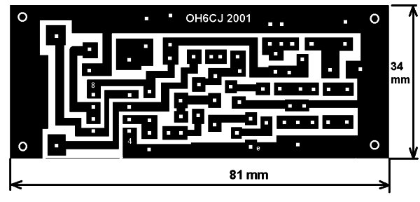
My pcb was designed using Free PCB software www.freepcb.com. The artwork contains both the main board and the display board on a single layout to save the cost of two separate boards. I purchased the pcb from www.4pcb.com by sending them the gerber files and using their “bare-bones” process. The “bare-bones” process does not include solder mask nor silk-screen. Just cut off the display board from the main board and mount it at a right angle to the main board and wire them together using the pads provided.

For more detail: PIC based WWVB clock

The post PIC based WWVB clock appeared first on PIC Microcontroller.
Contactless Digital Tachometer using PIC Microcontroller

$
0
0

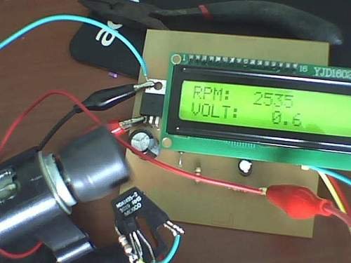
Hey friends, I should have posted this project last month itself  but there was some problem with the circuit. [link], author of this project did an exellent job. I have been watching him learning on this website. He came as a total noob but now he is well versed with 8051 and PIC microcontroller. earlier he has submitted Microcontroller Based Home Security SystemContactless Digital Tachometer using PIC Microcontroller

This project is about A Contactless Digital Tachometer. As per defination from wikipedia

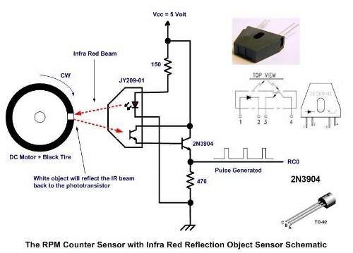
Following diagram explains the logic of this project.

The infra red reflective object sensor work by simply emitting the infra red beam and when it encounter the white object surface than the infra red beam will be reflected back to the phototransistor; next the phototransistor and the 2N3904 transistor which formed the Darlington pair will start to conduct and will generate enough voltage across the 470 Ohm resistor to be considered by the PIC16f690 microcontroller build in Capture Compare Pulse width modulation(CCP )module input port as the logical “1”. When the infra red beam encounters the black tire surface than both of the phototransistor and 2N3904 transistor will turn off; and the voltage across 470 Ohm resistor will drop to 3.5 volt (logical “0”).

Therefore by timing the generated pulse period by the infra red reflective object sensor we could easily calculate the RPM using this following formula:
Contactless Digital Tachometer using PIC Microcontroller schematic
Frequency = 1/T Hz; T is the generated pulse period in second.

RPM (Rotation per Minute) = Frequency x 60

Here is a sample video of working project:

You can download project related files here:

Download Contactless Digital Tachometer project

Thank you Romel for this contribution. If anyone has doubts regarding this project, please use forum.


For more detail: Contactless Digital Tachometer using PIC Microcontroller

Current Project / Post can also be found using:

  • course project Fire and security alarm on a microcontroller Pic
  • Home security projects using PIC micro controller
  • Usb ic pinout

The post Contactless Digital Tachometer using PIC Microcontroller appeared first on PIC Microcontroller.
PIC Industrial and Domestic Timer (Relay Controller)

$
0
0

Hi Friends,
I hope everyone had a rocking New year I was suppose to give you all a New year gift uploading a new project, but unfortunately it got delayed ‘coz I was busy with my *personal life*

One of our site member, Jeswanth kumar (jeswanthmg ) has submitted his project to me just before the new year eve. It took a little time for me to review this project.PIC Industrial and Domestic Timer (Relay Controller)

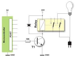
Project is titled “Industrial and Domestic Timer” is a time controller or a Time controlled relay project in simple words. Though it seems simple to say but the features of this project adds a great learning curve in both hardware and software part.

This project is buit around Microchip PIC Microcontroller PIC16F877A. Hardware includes DS1307 for time keeping, 16×2 LCD for display, 5 Push buttons and 8 relays. The alarm settings are stored in internal EEPROM of PIC microcontroller. The code for this project is written in C for Hi-Tech C Compiler.PIC Industrial and Domestic Timer (Relay Controller) schematic

Some Highlighting features are:

  • 32 alarm settings for 8 relays including on off but the number of alarms can easily be increased upto 46.
  • 16×2 LCD and 5 push buttons for user interface.
  • Microchip PIC16F877A as controller and DS1307 to manage time.
  • PIC16F877A’s internal eeprom to store alarm settings.
  • PIC’s code is written in Hi-Tech PIC C compiler.

Incase you face any kind of problem in this project feel free to post your doubts in forum.

Download Project: PIC Industrial and Domestic Timer (Relay Controller)


For more detail: PIC Industrial and Domestic Timer (Relay Controller)

Current Project / Post can also be found using:

  • clock pic
  • using pic to make clock
  • digital led time clock microcontroller programming
  • how to make digital on and off timer using microcontroller

The post PIC Industrial and Domestic Timer (Relay Controller) appeared first on PIC Microcontroller.
Introduction to Microchip PIC Assembler Language – Part 2

$
0
0

With only 35 instructions to learn the Microchip PIC microcontroller assembler language is considered very efficient and easy to learn; you will not find such as Atmel AVR microcontroller CP (compare) and BRNE (branch if not equal) or BRGE (branch if greater or equal) on the PIC microcontroller assembler language dialect, instead it’s just provide us with a very simple bit test and skip one line instruction. This fact is what makes programming the PIC microcontroller assembler language become very interesting and challenging, therefore although is easy to learn but for sure you will need a lot of flying time in order to code the PIC microcontroller efficiently.

The PIC Assembler Program Skeleton:

Continuing our lesson with the 8-bit, 8 pins midrange Microchip PIC12F683 microcontroller, I will start with the typical PIC microcontroller assembler program skeleton bellow:

The first part is the program comment; it’s always a good practice to put a comment to your program e.g. name, version, description, etc. All lines begin with ; sign is consider a comment to the MPASM (Microchip PIC Assembler) compiler.Introduction to Microchip PIC Assembler Language Part 2

The second part is the #include <p12F683.INC> MPASM compiler directive which tell the compiler to include the PIC12F683.INC file definition which exist in the c:\Program Files\Microchip\MPASM Suite directory (MPLAB IDE v8.00 default installation). This include file contain the standard PIC microcontroller physical address to the equivalent naming convention; for example instead of using the address 0x05 (5 hex) for general purpose I/O, we could use GPIO which is easier to remember.

The third part is the Microchip PIC microcontroller configuration bits register; this register is start at address 2007 on the PIC12F683 microcontroller and has 14 bits long. This register is one of the unique features of the PIC Microcontroller compared to other microcontroller, the PIC configuration bits could be configured on every startup of the program.

The configuration bits register is used to set how the PIC microcontroller work such as choosing the internal or external clock, using the master clear or not, etc. When programmed these bits will be read as “0“; for un-programmed these bits will be read as “1“. The following table shows the configuration bit used in our Hello World assembler program.

The complete description of this configuration bit could be found at page 84 on the Microchip PIC12F63 microcontroller datasheet; therefore by using the AND operator to the entire PIC MPASM configuration bit definition value we could configure the desire configuration bit register value or we could simply using just the bit value as shown on this following table:

Base on the configuration bit table shown above, we could set the PIC12F683 microcontroller configuration bit directly and this will give you the same result as the above program example:

The fourth part is the MPASM CBLOK 0x20 and closed with ENDC directive; which tell the MPASM compiler to map the Delay1 and Delay2 variables to the 8-bit general purpose registers which start at the address 0x20 on the PIC12F683 microcontroller address BANK 0; the Delay1 will be mapped to the general purpose register at the address 0x20 and the Delay2 will be mapped to the general purpose register at the address 0x21. The following picture show all the Microchip PIC12F683 microcontroller registers address which split into 2 groups named BANK 0 and BANK 1.

One of the unique things about the PIC microcontroller registers address comparing to other microcontroller that the address is not in one continues memory but its being split into two BANKS (groups); this mean we have to switch back and forth between the BANK addresses to access the desire register. For example if we want to access the register TRISIO, we have to switch to the BANK 1 before we could access it and switch back to the BANK 0 in order to access the GPIO register.

To make it easier to understand you could consider the BANK 0 and BANK 1 are like the DIRECTORIES in your computer file system, so if you want to access the TRISIO register (just like a file reside in your directory), you have to change the directory first to the BANK 1 before you could use this register and change directory back to the BANK 0 to access the GPIO register. If you notice some of the registers such as the STATUS register is shared or appeared to the both BANKS; this mean it doesn’t matter which BANK you are right now, you could always access this register. This is the same principal as the LINK file on the UNIX/Linux operating system file system, that one physical file could appear on many directories using just the link name.

The fifth part is the ORIGINATE (org) MPASM compiler directive that tell the MPASM compiler that your code is start at the address 0x0000 of the PIC microcontroller flash memory.

The sixth part is where you put your PIC assembler program code; this code could consist of main program and the subroutine or function.

The last part is the end MPASM compiler directive that tell the MPASM compiler that your code is end here and it’s a good practice to put the EOF (end of file) comment mark in your program so whenever you cut and paste the program to the other project you could make sure that all the codes is being copied until the EOF mark.

Inside the HelloWorld Program

Now we will walk through the program codes, first thing I will explain the initialization routine to the PIC12F683 microcontroller; in this initialization routine you will learn the top five of the 35 PIC12F683 microcontroller assembler instructions that you will certainly use in every project. Before we start make sure you have the PIC12F683 datasheet near you and open the page 101 on the Instruction Set Summary.

Start:
     bsf    STATUS,RP0    ; Select Registers at Bank 1
     movlw  0x70
     movwf  OSCCON        ; Set the internal clock speed to 8 Mhz
     clrf   TRISIO        ; Set all General Purpose I/O to output
     clrf   ANSEL         ; Make all ports as digital I/O
     bcf    STATUS,RP0    ; Back to Registers at Bank 0

The first thing in our initialization routine is to set the internal clock speed which can be controlled in the oscillator control register or OSCCON at BANK 1, we decide to run the PIC12F683 microcontroller with the maximum internal clock speed of 8 Mhz as shown on the OSCCON register bellow:

By making the internal oscillator selection bits IRCF2=1, IRCF1=1 and IRCF0=1 on the OSCCON register we select the 8 Mhz of internal oscillator frequency, this could be written as the following C program:

But in the PIC assembler code, before we could use the OSCCON register we have to change to the BANK 1, since the default BANK when the PIC microcontroller power up is in the BANK 0; How to instruct the PIC microcontroller to change to the BANK 1; this could be done by setting the bank selection register bits RP1 and RP0 on the STATUS register.

Because the PIC12F683 microcontroller only have two BANKS, then the RP1 bit is not use; but for some PIC microcontroller families such as PIC16F690 or PIC16F886 families have four BANK addresses; therefore for this PIC microcontroller families both RP1 and RP0 bits are used to select the BANK addresses. By setting the bit RP0 to logical “1” we instruct the PIC12F683 microcontroller to change to the BANK 1 and by clearing the bit RPO to logical “0“, we instruct the PIC12F683 microcontroller to change back to the BANK 0 (default). The famous PIC set and clear bit oriented file register operation could be used to achieve this task.

bsf f,b -> Bit Set f: Register Address (0x00 to 0x7F) and b: is the bit address
bcf f,b -> Bit Clear f: Register Address (0x00 to 0x7F) and b: is the bit addressIntroduction to Microchip PIC Assembler Language Part 2 schematic

bsf    STATUS,RP0    ; Select Registers at Bank 1

This instruction will simply tell the PIC microcontroller to SET the RPO bit (the fifth bit) on the STATUS (address 0x03) register and to CLEAR the RPO bit on the STATUS register we use this command bellow:

bcf    STATUS,RP0    ; Back to Registers at Bank 0

As you seen from time to time we have to change the BANK address in order to access the desired registers and we always use the STATUS register to achieve this task; therefore now you understand why the PIC microcontroller shared this STATUS register through all the PIC’s BANK addresses, so you could always access this important register regardless of the BANK address you are in right now.

After we change to the BANK 1 in order to assign the 0x70 value into the OSCCON register, we have to put first the value in the PIC microcontroller 8-bit accumulator register named WREG (working register) and then move this accumulator value into the OSCCON register. Again the two most used PIC assembler instructions will be used to achieve these tasks:

movlw k -> Move literal (constant) to WREG, k is the 8-bit constant
movwf f -> Move the WREG value to f: Register Address (0x00 to 0x7F)

movlw  0x70
movwf  OSCCON        ; Set the internal clock speed to 8 Mhz

The tri-state register TRISIO and the analog selection register ANSEL located at BANK 1 are used to set the PIC microcontroller I/O port behavior:


For more detail: Introduction to Microchip PIC Assembler Language – Part 2

The post Introduction to Microchip PIC Assembler Language – Part 2 appeared first on PIC Microcontroller.
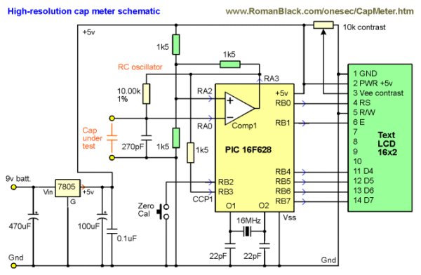
100MHz frequency counter with PIC16F628A – LCD Display

$
0
0

This project shows how to build a very simple yet very useful tool that every DIY enthusiast should have in his lab: a 100MHz+ frequency counter.

The schematic is fairly simple and straightforward and uses a PIC16F628A microcontroller for measuring frequency and a high speed comparator for signal amplification and conditioning.

The microcontroller uses its internal 4MHz oscillator for the CPU clock. Timer1 uses an external crystal resonator (watch crystal) with 32768Hz frequency for setting the 1 second time base.


Timer0 is used to count the input signal at pin RA4.

The max frequency of Timer0 is 1/4 of the CPU clock which is 1MHz, but there is internal prescaler and it can be set from 1 to 256. In theory this can allow the input signal to be up to 256MHz. On the other hand, in the datasheet of 16F628A there is a requirement for the input pulse at RA4 to be with minimum width of 10ns which is 100MHz frequency. So the maximum frequency can be between 100Mhz and 256MHz. I checked with two different PIC16F628A and they easily go over 200Mhz barrier.

In order to achieve the maximum possible resolution, the input signal is probed for 0.125 seconds and the prescaler value is computed accordingly. This way when input frequency is below 1Mhz the resolution will be 1Hz.

The most important part for the accuracy of the frequency counter is the time base setting circuit – crystal resonator X1 and capacitors C4 and C5. C4 and C5 values can be between 33pF and 62pF and the crystal frequency can be fine tuned with them.

The input of the schematic is feed through a high speed comparator. In order to switch with 100+ Mhz frequency the comparator must have propagation delay bellow 5ns. In this schematic I used Texas Instruments TLV3501 with 4.5ns delay. This was cheapest high speed comparator I was able to find (2.5 euro).

The two inputs of the comparator are set at about 1/2 of power supply voltage with 15-25mV difference between them so any AC signal with higher voltage will start switching the comparator.

If there isn’t input signal the output of the comparator stays low. If we connect a signal source to the positive input, when the signal goes over +20mV the comparator switches high (5V), when signal goes bellow +20mV comparator switches back to 0V. So whatever signal we fed to the input, the output is square wave 0V-5V with the same frequency as the original signal.

For more detail:  100MHz frequency counter with PIC16F628A – LCD Display100MHz frequency counter with PIC16F628A – LCD Display

The post 100MHz frequency counter with PIC16F628A – LCD Display appeared first on PIC Microcontroller.
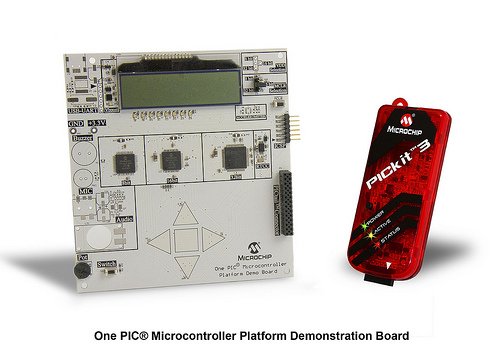

PIC Programmer and Programming

$
0
0

Programmer

There are many PIC programmers you can purchase or whose schematics (and software) you can find freely over the Internet

David Tait has a programmer with software and hardware schematics available here. If you read his documentation, you will find various programmer schematics. I use the Classic “Tait” Programmer. The schematic is below:PIC Programmer and Programming

I have modified my Tait programmer to include a programming header consisting of GND, MCLR, RB6 (CLOCK), and RB7 (DATA) for use in programming “in circuit”. Most of my microcontroller project schematics include a pull-up resistor on MCLR, so you can use the programmer with no further modifications.
Programmer Software

I don’t use FPP, the software supplied by David Tait. You can use it and program a PIC16F877 to run the oscilloscope firmware and everything should work just fine. If you want to program the more readily available (and generally cheaper) PIC16F877A, FPP won’t work.PIC Programmer and Programming schematic

Therefore, I use another free programmer software called WinPic800 (you can also use another program called IC PROG). I prefer WinPic800 because it is easier to set up in Windows XP (you don’t have to go download a separate driver), it is flexible enough to work with non-standard programmers, and I get consistently good results.

To help with the setup, here is a screen capture of the Hardware Settings dialog from WinPic800 configured for use with the Tait Programmer on LPT1. Notice the bit numbers and byte offsets for each signal and which signals are inverted.

Once you’ve worked through these items above, you should now be ready to program the PIC!

The post PIC Programmer and Programming appeared first on PIC Microcontroller.
PIC Based Oscilloscope Clock

$
0
0

For those are not into electronics, you must know that an oscilloscope has basically only one timebase to move the spot horizontally from left to right with the same intensity. The vertical deviation is function to the input voltage. You understand immediately that you can’t directly display 7 segment digits, because you can’t move the spot from right to left.

By using X/Y mode, where the spot is controlled on two axes by two different voltages, it is possible to draw a picture (as in the examples mentioned above), but a fast digital to analog converter with two channels and at least 8 bits of resolution would be needed.PIC Based Oscilloscope Clock

So we have to deal with a spot that always goes from left to right in the same period of time.
If we want to have a 7segment-like display, we have to draw :

vertical segments : easy to do, just change voltage up and down quickly a few times.
horizontal segments : easy to do, just set a voltage level and keep it as long as you need.

By using 2 PIC outputs and a basic R2R digital to analog converter, we can have up to four different voltage levels : 3 for the vertical segment, and another one where to put the spot when it is not in use to draw a segment.

But the problem is that a 7 segment digit may have up to 3 horizontal lines at a time (like 2, 3, 8, 9..) but we can draw only one during one spot deviation.
So we will have to cheat with retinal persistence and use multiple frames : since we can have only one vertical segment per period, three periods will be needed to draw a full 7 segment digit.

Supposing we want to display 12:34:56 on the screen :

During the first period, we will draw all vertical segments, and horizontal upper segments only :

As a game, I let you try to find out the spot trajectory.
Don’t forget the rules :PIC Based Oscilloscope Clock schematic

you can’t go backward
you can’t clear the spot

But you can move so fast vertically that the eye can’t see the spot moving.

The lowest line under the digits is not significant, it his the place where the spot is parked when not used to draw a segment.


For more detail: PIC Based Oscilloscope Clock

Current Project / Post can also be found using:

  • Mikroc pic timers for hourclock

The post PIC Based Oscilloscope Clock appeared first on PIC Microcontroller.
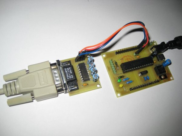
Hello World Project With PIC Microcontroller – Part II

$
0
0

Hello Friends, Welcome back. In the last tutorial we started working with MPLab and HI-TECH C Compiler and written our first C program to blink LED. After compiling the program we got the HEX file. Now, in this tutorial we will see how to transfer(burn) the hex file to our Microcontroller chip and then power it up to actually blink the LED.

We will use eXtreme Burner – PIC , which is a easy to use GUI programmer for PIC18 MCUs. The burner supports USB connectivity with PC so it is very easy to install and use.

Launch eXtreme Burner – PIC from Windows Desktop or Start Menu.Hello World Project With PIC Microcontroller – Part II

Fig.: eXtreme Burner – PIC, Main Screen.

The software is easy to use. First you need to load the HEX file which was generated by MPLAB+HI-TECH C in previous tutorial. So select Open from File Menu or From the Toolbar. Then select the hex file. Now the HEX file will be loaded and the contents (FLASH,EEPROM,Chip Settings) will be available.

Now connect the programmer with your PC by using standard USB Cable the programmer will be automatically detected by software (provided drivers are installed previously) . Apply power to programmer using a 12v DC adaptor. Place a PIC18F4550 chip in the ZIF socket and lock it.

Fig.: eXtreme Burner – PIC, USB Programmer for PIC Micros.

After that select PIC18F4550 from Chip Menu and Programming Mode = ZIF Socket from Settings Menu. You are now ready Burn !!!

Select Write All From Toolbar or Write Menu.

The burner will start the Burn Process. It will write each section of memory and verify that they are written correctly.

Fig.: eXtreme Burner – PIC, Burning in Progress.

After few seconds the process ends. The chip is now programmed with the provided HEX file contents. The chips settings have also been modified to suit the hardware environment we will be using. These settings were also embedded in the HEX file (more on this topic in latter tutorial). And it got into the HEX file from the C file. Notice the two linesHello World Project With PIC Microcontroller – Part II schematic

__CONFIG(1,0x0F24);
__CONFIG(2,0X0000);

in the C file of previous tutorial.

The chips is now ready for some amazing lighting effects !

Get the following to see that in action

A Breadboard.
A 20MHz Crystal
1 x 330 Ohms resistor
1 x 4.7k resistor.
2 x 22pF Ceramic Disk Type Capacitor.
A LED
Some Bread boarding wires (free if you buy Breadboard from above link)

Go ahead and connect them like this.


For more detail: Hello World Project With PIC Microcontroller – Part II

The post Hello World Project With PIC Microcontroller – Part II appeared first on PIC Microcontroller.

PIC microcontroller ATA library

$
0
0

This project started life a long time ago, with the intention to build an iPod clone, back when personal MP3 players were an expensive luxury and long before you could buy them from China on ebay for less than a light bulb.

The plan for the MP3 player was to use a PIC microcontroller connected to a PATA hard disc drive (They were just called ATA back then, before SATA came along), the PIC would read MP3 files from a FAT32 partition on the drive and send them to an MP3 decoder chip through an audio DAC to earphones/speaker. A monochrome LCD with buttons would have provided the usual player controls and track selection, with a laptop hard drive giving plenty of song storage. I was going to mount all of this in a head unit in the dashboard of my car.

Unfortunately the project got shelved for about 10 years, until recently when I wanted my breadboard back. By now my car stereo has a USB socket to plug in mass storage and an SD card slot. So in order to bring this project to some sort of useful end, I finished off the library code I had written that provides access to files from a FAT32 filesystem on an ATA hard disc or CompactFlash with a PIC.

So the ATA+FAT32 library is detailed here. It is a bit special, in that it is strongly suited to low RAM systems, and I mean looooowwwww RAM. I’ve had the ATA access code running on a PIC16F877 which only has 368 bytes of RAM. To get the FAT32 access in, I did have to go to a PIC18F452, which has about 1600 bytes or so of data RAM. If 368 bytes of RAM sounds like a typo (It isn’t), bear in mind that PICs are based on a Harvard architecture, so the program memory, where the .text section of your program is stored, is counted seperately from the data RAM.PIC microcontroller ATA library

The astute reader will be wondering at this point how a 512 byte sector can be read from a hard disc into only 368 bytes of RAM. The answer is that it isn’t. The API for the library is written in such a way that no complete sector is ever read at once. The caller of the library is able to set the LBA address for a read, the bytes of the sector are then read and examined, or skipped, as is needed by the calling code. Using this technique, even the FAT32 code, which provides read only access to files and directory entries, never needs to read a full sector.

Get the source code: from github.

The rest of this page is extra detail, which may come in useful if you happen to decide to use the library in your own project.

The Hardware

The circuit to connect the PIC micro to the ATA hard disc signals is based on a design used by Paul Stoffregen in his Using an IDE Hard Drive with a 8051 Board and 82C55 Chip project.

I captured the schematic in Eagle format, available here and shown below.

As can be seen in the circuit, an 8255A port expander is used to get the multitude of ATA signals down to a more sensible amount, in order to leave enough I/O on the micro to hopefully perform other functions. The 74HC04 inverters used on some of the ATA control lines between the 8255 and the drive are very much necessary. This is because when any of the 8255 port directions are changed via its one internal control register, all bits on the 3 ports are reset to zero. Some of the ATA signals are active low, so without the inversion, setting them low at the drive would cause an inadvertent read or write to the currently addressed ATA register in the drive, or reset the drive entirely.

Because I was holding off laying out a board until the other MP3 player components were added, the circuit was built up using jumper wires on a breadboard.

The Software

The library is written in C and can be built with either Microchips current XC8 compiler, or the now obsolete and quite old Hi-Tech PICC or PICC18 (I was using version 8, which is even older). Note that the code needs no changes between these two compiler suites apart from including a different header file. This is because Microchip bought Hi-Tech and if you look deeper into the header files, PICC is referenced a lot and the compilers are pretty much the same.

The ATA routines in the library are written for the 8255 circuit shown above, but there is some flexibility in which pins and ports are used on the PIC for the various signals. Simply change the #defines in the clearly commented sections within picata.c to account for any differences in pin assignment.

The ATA API described in picata.h provides the expected init routine, a get info function which reads off only the model/serial and drive geometry values, more as a check that the drive access is working than for any useful function, hence that can be disabled with a #define. As mentioned above, data access is performed by seperate API functions, one to set the LBA address of the required sector, another to read the next byte in the sector straight from the drive, and another to skip a given number of bytes in the sector.

Beneath the API functions, the next layer down deals with accessing ATA registers (See the ATA spec for details), and the bottom layer of functions deals with twiddling with the 8255 in order to waggle the ATA control signals on port C, whilst outputting register data or reading it back from ports A and B, being sure to reverse the port directions in the 8255 mode register at the appropriate points.

Initially, I had some 8255 port read/write routines which would automatically switch port directions in the control word as they went along. A single access to an ATA register requires numerous port accesses through the 8255, to toggle control and address signals to the drive on port C, read the register data through port A etc. Eventually I realised it was the 8255 mode register changes clearing all outputs, as explained above, which were negating the ATA chip select halfway through the ATA register access cycle.

Whilst trying to get the ATA register accesses working correctly, I wired up a logic analyser I had to hand, to see what the signals were doing.

The code was then re-written with the explicitly layered approach, the ATA register access routines now call down a layer to set the 8255 port directions at the beginning of the ATA access.

Bad Signals

Once the waveforms for accesses of the low byte of the ATA data bus were looking good, I found that all the high bytes of the 16 bit data word accessed during sector data reads had consistent bit errors. Some of the logic analyser connections were moved to those data[8:15] signals, which then revealed a lot of ringing or oscillation of the logic level on one bit or another.

This was solved in a highly technical fashion by having the demo code discussed below looping repeatedly on the PIC, then while that was gunning away, reaching over and poking the wires on the breadboard with my finger. With enough prodding suddenly good data would get read out. Must have been a poor ground or some crosstalk, after that every so often the IDE cable would need a good nudge, having discovered the sweet spot.PIC microcontroller ATA library schematic

Wiring Test

Whilst trying to diagnose the signal noise issue, I suspected there may be a wiring fault, and so a walking ones test for all pins on the 8255 ports was added. The logic analyser probes were then connected to the same rails as the ATA hard drive IDC header on the breadboard. It was only by moving the probe wires to the rest of the ATA data pins to see the test working, that the noise was caught.

The Demo

There is some demonstration code in main.c, which does the following:

*Perform the wiring test if ATA_USE_WIRINGTEST is defined *Print contents of drive sector 0 *Print contents of FAT32 BPB sector *Read drive info if ATA_USE_ID is defined *Print all drive info bytes if HD_INFO_DBG is defined *Print a summary of drive model/serial/revision strings, drive geometry (Meaningless nowadays) *Initialise FAT32 if FAT32_ENABLED is defined *Parse the entries of the root directory, printing the files and directories found *Open a file named HELLO.TXT if present, and print the contents


For more detail: PIC microcontroller ATA library

The post PIC microcontroller ATA library appeared first on PIC Microcontroller.
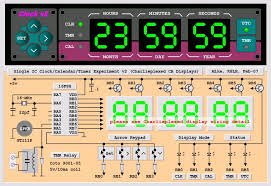
How to make a ‘Propeller Display’ using PIC microcontroller

$
0
0

This is my first post Related to Projects and today i will describe ‘Propeller Display’ project. Me and my friend Rushi, we both made ‘Propeller Display’ project during our under-graduation. Below is the photo of the project.

Project uses Microchip PIC16F84A Microcontroller. Below is the brief specification for same.
  • 18-Pin, 8-bit microcontroller
  • Operating Speed – 20MHz max.
  • 1024 words of program memory (word length – 14 bits)
  • 68 bytes of Data RAMHow to make a 'Propeller Display' using PIC microcontroller
  • 68 bytes of Data EEPROM
  • 14-bit wide instruction words
  • 8-bit wide data bytes
  • 15 special purpose registers
  • Four interrupt sources: Ext. RB0/INT pin, TMR0 overflow, PORTB<7:4> interrupt-on-change, Data EEPROM write complete
The principle of this project is perception of Vision(POV). Quating from Wikipedia,
“Persistence of vision is the phenomenon of the eye by which an afterimage is thought to persist for approximately one twenty-fifth of a second on the retina.”
 From the definition we can understand that our retina retains the view of past image for approximately  1/125 sec = 0.008 sec. Lets, consider a example of torch, if one project the light-spot on wall, further he moves the light-spot circle back and forth horizontally and gradually increases the speed. Then at a time, eye of viewer can not differentiate the light-spot circle and it is viewed as one straight horizontal line of light instead of circle.Same idea applies here. In propeller display, continuous projection of LED’s patterns (Some LEDs are ON and others are OFF) at specific location with rotating entity, gives visual appearance as steady patterns.How to make a 'Propeller Display' using PIC microcontroller schematic
Below is the Schematic of project. We have used Jon stanley’s propeller clock as Reference design.
Components:-
Microchip PIC16F84A      1
10K ohm resister      5
120 ohm resister      7
4 MHz crystal oscillator      1
220 µF capacitor      1
3 mm yellow LED      7
On/Off Control switch      1
DC motor      1

Requirements:-

  • 9V battery to power circuit on breadboard (which will be converted into 5V)
  • 12V volt variable power supply for DC motor
  • ICSP programmer


For more detail: How to make a ‘Propeller Display’ using PIC microcontroller

The post How to make a ‘Propeller Display’ using PIC microcontroller appeared first on PIC Microcontroller.

Viewing all 202 articles
Browse latest View live


<script src="https://jsc.adskeeper.com/r/s/rssing.com.1596347.js" async> </script>