The seven segment display is one of the most popular numeric displays used in many microcontroller applications because it’s cheap, robust and reliable. The seven segments actually consists of 8 LED (Light Emitting Diode) and it’s come with various sizes suitable for various numeric display application such as digital clock, counter, thermometer, humidity, etc. On this project we are going to show you how to drive this type of display and this time we will use the Microchip PIC16F886 microcontroller to display the room’s temperature both in Centigrade and Fahrenheit scale.
The Seven Segments Display
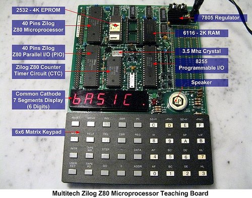
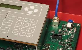
Many years ago before the LCD (Liquid Crystal Display) come into the arena, the seven segments display is the main player; it’s so popular and its use in almost everything not just to display the numeric value but also a character as well, such as my old Multitech Zilog Z80 microprocessor teaching board to run the BASIC language interpreter bellow:
From the above picture you could see how complex the circuit was on those days; the circuit consists of separate IC such as 8-bit microprocessor (Zilog Z80), counter timer circuit (CTC), 4K EPROM (Erasable Programmable ROM, this ROM type can be erased only by exposing it to the UV lamp) for the firmware (the board basic I/O function and BASIC language interpreter), 2K RAM for the program and the I/O controller. Thanks to today technology this complex circuit is already put into single chip known as the microcontroller and we don’t have to use this UV lamp to erase the program anymore (you must be laugh right know, but on those days that’s the only way to do it) but what remain the same is; we still use this seven segments display, mostly for displaying the numeric value.
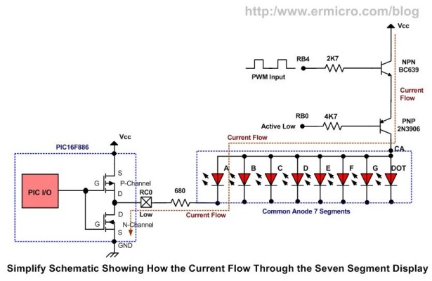
There are two types of seven segments available on the market known as common anode (CA) and common cathode (CC):
Displaying the seven segments is just a matter of applying the correct forward bias voltage to each of the LED’s segment in the seven segments package; for example if we want to show the digit “3” than we have to apply the forward bias voltage on each of the A, B, C, D and G LED segments. The segment pins out is vary among the types and the brands, therefore you have to find out the correct pins for each segments and the common pin as well before you can start to use it.![Seven Segment Display Thermometer with PIC Microcontroller]()
The Room’s Temperature Project
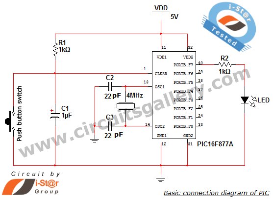
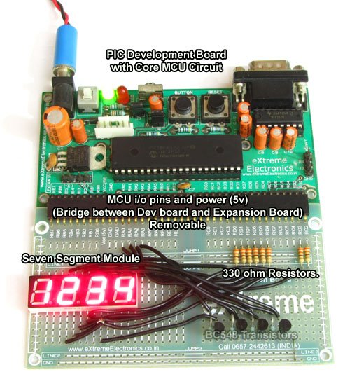
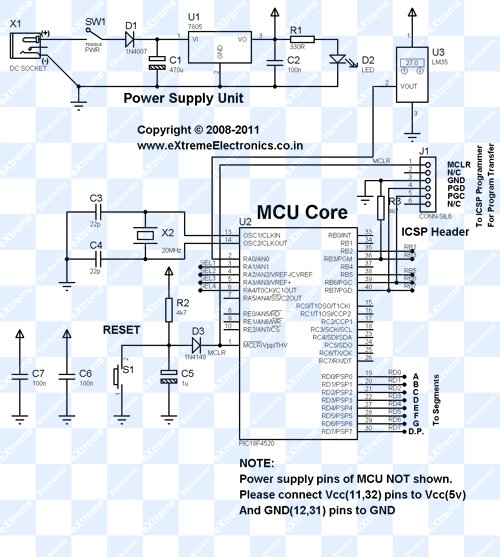
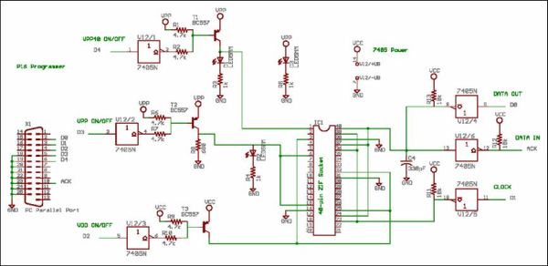
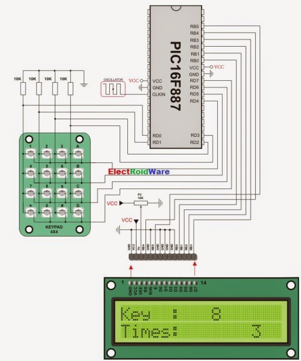
Our room’s temperature project is use 4 seven segments display for displaying the room’s temperature. The heart of this room’s temperature project is the 8-bit 28 pins midrange Microchip PIC16F886 microcontroller (for those with the Atmel AVR background this microcontroller is comparable to the AVR ATMega8 or ATMega88 microcontroller families). The following is the complete schematic design for this project:
The designed I’ve made here not solely to show the room’s temperature with the seven segments, but it serve as the good learning tools as well, as we will explore the PIC 16F886 features such as ADC (Analog to Digital Converter), PWM (Pulse Width Modulation) and the timer counter capabilities in one shoot. Ok now lets fasten your seat belt as we will run through the design concept here.
First is the display, all the common anode seven segments are connected to PIC 16F886 microcontroller’s port RC0 to RC7, because the microcontroller’s port I/O could not sink the 8 LEDs current all together so we use the 2N3906 PNP transistor (T1 to T4) to sink the current; you could read more about sinking and sourcing I/O port in Powering Your Microcontroller Project article posted on this blog. Differ from usual design I put the NPN BC639 transistor (T5) for driving the four PNP transistors (T1 to T4) with the PWM signal in order to control the seven segments display contrast.
The display contrast is controlled by the LDR (light dependent resistor) together with 10K trimpot serve as the voltage divider input to the PIC16F688 microcontroller analog port AN1; by detecting the light intensity captured by the LDR, this room’s temperature circuit will automatically adjust the seven segments display contrast according to the room’s light intensity. The darkest the room’s the brightest the seven segments display and vise verse.
Secondly the temperature sensor, on this circuit we use the National Semiconductor LM35DZ precision centigrade temperature sensor. The LM35DZ will produce linear voltage output of 10 mV for each degree of the temperature increment in centigrade scale. Together with the 1 Volt voltage reference input provided by 10K trimpot (R17) on the PIC16F886 microcontroller’s VRef+ (4) and VRef- (5) pins, we could precisely measure the room’s temperature on the PIC16F886 microcontroller’s analog port AN0.
The last is the S1 switch, this switch is use as the toggle switch to choose the room’s temperature scale: Centigrade or Fahrenheit. The following table shows the Microchip PIC16F886 microcontroller ports used in this project:
The following is the list of hardware and software used in this tutorial:
1. Resistor: 680 Ohm (8), 4K7 (4), 2K7 (1), 10 K (1)
2. Two Trimpot: 10 K
3. One LDR (Light Dependent Resistor)
4. Capacitor: 100nF (1), 10nF (1)
5. One Micro Switch
6. Transistor: NPN BC639 (1), PNP 2N3906 (4)
7. National Semiconductor LM35DZ precision centigrade temperature sensor (TO-92)
8. 4 Common Anode Seven Segments Display
9. Microchip PIC16F886 Microcontroller
10. Microchip PICKit2 Programmer
11. Microchip MPLAB IDE v8.0 or higher
12. HI-TECH C PRO for the PIC10/12/16 MCU family V9.60PL5 (you could not use the HI-TEC PICC Lite version on the Microchip PIC 16F886 microcontroller, but you could use the Hi-TECH C PRO in Lite Mode).
Now let’s take a look at the C code that makes this thing happen:
// ***************************************************************************
//  File Name    : pictemp.c
//  Version      : 1.0
//  Description  : PIC Thermometer
//  Author       : RWB
//  Target       : Microchip PIC16F886 Microcontroller
//  Compiler     : HI-TECH C PRO for the PIC10/12/16 MCU family V9.60PL5
//  IDE          : Microchip MPLAB IDE v8.00
//  Programmer   : PICKit2
//  Last Updated : 28 Feb 2009
// ***************************************************************************
#include <pic.h>
/*   PIC Configuration Bit:
**   INTIO      - Using Internal RC No Clock
**   WDTDIS     - Wacthdog Timer Disable
**   PWRTEN     - Power Up Timer Enable
**   MCLRDIS    - MCLR functions as IO
**   UNPROTECT  - Code Un-Protect
**   DUNPROTECT - Do not read protect EEPROM data
**   BORDIS     - Brown Out Detect Disable
**   IESODIS    - Internal External Switch Over Mode Disable
**   FCMDIS     - Monitor Clock Fail Safe Disable
**   BORV21     - Brown Out Reset 2.1 Volt
*/
__CONFIG(INTIO & WDTDIS & PWRTDIS & MCLRDIS & UNPROTECT & DUNPROTECT & \
  BORDIS & IESOEN & FCMDIS & LVPDIS & DEBUGEN);   // Address 0x2007
__CONFIG(BORV21);                                 // Address 0x2008
// Using Internal Clock of 8 MHz
#define FOSC 8000000L
// Variable Used for Thermometer
#define LDR_THRESHOLD 50
#define MAX_DCYCLE 255
const char SSEG[] = {
  0b11000000,  // 0, LED Segment: A,B,C,D,E,F
  0b11111001,  // 1, LED Segment: B,C
  0b10100100,  // 2, LED Segment: A,B,D,E,G
  0b10110000,  // 3, LED Segment: A,B,C,D,G
  0b10011001,  // 4, LED Segment: B,C,F,G
  0b10010010,  // 5, LED Segment: A,C,D,F,G
  0b10000010,  // 6, LED Segment: A,C,D,E,F,G
  0b11111000,  // 7, LED Segment: A,B,C
  0b10000000,  // 8, LED Segment: A,B,C,D,E,F,G
  0b10010000,  // 9, LED Segment: A,B,C,D,F,G
  0b11000110,  // C, LED Segment: A,D,E,F
  0b10001110   // F, LED Segment: A,E,F,G
};
unsigned char DispDigit[4];
unsigned char DigitCount;
unsigned char TempType;
static void interrupt isr(void)
{
  if(T0IF) {			    // TIMER0 Interrupt Flag
    /* Pull Low the Segment */
    PORTC = DispDigit[DigitCount];
    /* Activate the Digit and Advanced to next Digit */
    PORTB = ~(1 << DigitCount++);

    /* Reset the Digit Count */
    if (DigitCount > 3)
      DigitCount=0;

    TMR0 = 156;             // Initial Value for 3.2 ms Interrupt
    T0IF = 0;			    // Clear TIMER0 interrupt flag
  }
}
// Delay Function
#define _delay_us(x) { unsigned char us; \
	  	       us = (x)/(12000000/FOSC)|1; \
		       while(--us != 0) continue; }
void _delay_ms(unsigned int ms)
{
  unsigned char i;
  do {
    i = 4;
    do {
      _delay_us(164);
    } while(--i);
  } while(--ms);
}
/* Seven Segment Put Number: Implementing floating value from 0 to 99.9 */
void SSEG_putnum(float number)
{
   unsigned char iDigit,iDigit1,iDecimal;
if (number > 99.9) return;
   /* Global interrupt disable */
   GIE = 0;

   iDigit=number;                        // Convert float to Integer
   iDecimal=(number - iDigit) * 10;      // Get The Decimal Digit
   DispDigit[1]=SSEG[iDecimal];          // First Decimal Digit
   if (iDigit >= 10) {
     iDigit1=iDigit / 10;
     DispDigit[3]=SSEG[iDigit1];         // Second Digit
     iDigit=iDigit - (iDigit1 * 10);
   } else {
     DispDigit[3]=SSEG[0];               // Zero Sign Second Digit
   }
   DispDigit[2]=SSEG[iDigit] & 0x7F;     // First Digit with Decimal Point
   /* Global interrupt enable */
   GIE = 1;
}
void main(void)
{
  unsigned int iValue,iCTemp;
  unsigned char ldr_value;
  float CentTemp;

  OSCCON=0x70;         /* Select 8 MHz internal clock */

  TRISA = 0xFF;        // Input for RA0 to RA7
  TRISB = 0x00;        // Output for RB0 to RB7
  TRISC = 0x00;        // Output for RC0 to RC7
  ANSEL = 0b00000011;  // Set PORT AN0 and AN1 to analog input AN2 to AN7 digital I/O
  ANSELH = 0b00000000; // Set Other as Digital I/O
  /* Initial Output Port */
  PORTC=0xFF;
  PORTB=0xFF;
  /* Init TIMER0: Period: 1/(Fosc/4) x Prescaler x TMR0
     0.0005 ms x 64 * 100 = 3.2 ms */
  OPTION = 0b00000101; // 1:64 Prescaler
  TMR0=156;            // Interrupt every 3.2 ms
  T0IE = 1;	       // Enable interrupt on TMR0 overflow
  GIE = 1;	       // Global interrupt enable
  /* Init PWM for Single Output */
  CCP1CON=0b00001100;  // Single PWM mode; P1A, P1C active-high; P1B, P1D active-high
  CCPR1L=MAX_DCYCLE;   // Start with Max Duty Cycle
  T2CON=0b00000101;    // Postscaler: 1:1, Timer2=On, Prescaler = 1:4
  PR2=0x65;            // Frequency: 4.90 kHz
  TMR2=0;              // Start with zero Counter
  PSTRCON=0b00001000;  // Enable Pulse Steering on P1D (RB4)
  /* Initial variables used */
  DigitCount=0;
  TempType=0;                // Centigrade Type
  DispDigit[0]=SSEG[10];     // Centigrade Sign
  DispDigit[1]=SSEG[0];      // Zero Digit
  DispDigit[2]=SSEG[0];      // Zero Digit
  DispDigit[3]=SSEG[0];      // Zero Digit
  for(;;) {
    /* Get First Sample */
    ADCON0=0b11000001;       // Select the FRC for 8 MHz. ADC port channel 0, Turn On A2D
    ADCON1=0b10110000;       // Right Justified, Vref: VCFG1 and VCFG0 (1 Volt Reference)
    GODONE=1;	             // initiate conversion on the channel 0
    while(GODONE) continue;  // Wait conversion done
    iValue=ADRESL;           // Get the 8 bit LSB result
    iValue += (ADRESH << 8); // Get the 2 bit MSB result
    iCTemp = iValue;
    _delay_ms(50);
    /* Get Second Sample */
    GODONE=1;	// initiate conversion on the channel 0
    while(GODONE) continue;  // Wait conversion done
    iValue=ADRESL;           // Get the 8 bit LSB result
    iValue += (ADRESH << 8); // Get the 2 bit MSB result
    iCTemp += iValue;
    _delay_ms(50);
    /* Get Third Sample */
    GODONE=1;	// initiate conversion on the channel 0
    while(GODONE) continue;  // Wait conversion done
    iValue=ADRESL;           // Get the 8 bit LSB result
    iValue += (ADRESH << 8); // Get the 2 bit MSB result
    iCTemp += iValue;

    /* Calculate the Average Centigrade Value */
    /* (ADC Value/10.24) / Vref, LM35DZ Out=10mV/C, Vref = 1 Volt */
    CentTemp=(iCTemp/3.0)/ 10.24;
    /* Read the Light Sensor */
    ADCON0=0b11000101;       // Select the FRC for 8 MHz. ADC port channel 1, Turn On A2D
    ADCON1=0b00000000;       // Left Justified, Vref: Vss and Vdd
    GODONE=1;	             // initiate conversion on the channel 0
    while(GODONE) continue;  // Wait conversion done
ldr_value = ADRESH; // Get the LDR Value, Ignore the LSB on ADRESL
    if (ldr_value > LDR_THRESHOLD)
     ldr_value = LDR_THRESHOLD;
CCPR1L=MAX_DCYCLE - (5 * ldr_value); // Set the PWM Duty Cycle
    /* Read the RA4 Switch */
    if (RA4 == 0) {              // Change the Thermometer Type when pressed
      _delay_ms(1);
      if (RA4 == 0) {            // Read again for Simple De bounce
        TempType=~TempType;      // Change Type Flag
      }
    }
    /* Set the Temperature Type */
    if (TempType) {
      /* Fahrenheit = 9/5 x Centigrade + 32 */
      CentTemp=((9.0/5.0) * CentTemp) + 32;
      DispDigit[0]=SSEG[11];     // Fahrenheit Sign
    } else {
      DispDigit[0]=SSEG[10];     // Centigrade Sign
    }

    /* Now Display The Result */
    SSEG_putnum(CentTemp);
    _delay_ms(200);
  }
}
/* EOF: pictemp.c */
Multiplexing with PIC TIMER0
As you’ve seen from the schematic above, displaying the entire seven segments digits at the same time would be not possible because every digit will have different information to be displayed, in other word every digit will display different LED segment combination; therefore the solution is to display it one at the time. If we display the four seven segment digits in sequence fast enough, it will appear (give an illusion) to our eyes as we display all these segments simultaneously; this method is called multiplexing.
The multiplexing algorithm is best implemented using the PIC timer/counter TIMER0 peripheral; by letting the TMR0 counter register to overflow and generate interrupt every 3.2 ms, we could display each of the seven segments digit every 3.2 ms; the total time to complete displaying the whole digits is about 12.8 ms (4 x 3.2ms) and this time is already sufficient to avoid flicking appear to our eyes (you could read more about PIC TIMER0 peripheral on the Basic Servo Motor Controller with Microchip PIC Microcontroller article posted on this blog).
The following is the C code that implements this algorithm:
const char SSEG[] = {
  0b11000000,  // 0, LED Segment: A,B,C,D,E,F
  0b11111001,  // 1, LED Segment: B,C
  0b10100100,  // 2, LED Segment: A,B,D,E,G
  0b10110000,  // 3, LED Segment: A,B,C,D,G
  0b10011001,  // 4, LED Segment: B,C,F,G
  0b10010010,  // 5, LED Segment: A,C,D,F,G
  0b10000010,  // 6, LED Segment: A,C,D,E,F,G
  0b11111000,  // 7, LED Segment: A,B,C
  0b10000000,  // 8, LED Segment: A,B,C,D,E,F,G
  0b10010000,  // 9, LED Segment: A,B,C,D,F,G
  0b11000110,  // C, LED Segment: A,D,E,F
  0b10001110   // F, LED Segment: A,E,F,G
};
unsigned char DispDigit[4];
unsigned char DigitCount;
if(T0IF) {		      // TIMER0 Interrupt Flag
  /* Pull Low the Segment */
  PORTC = DispDigit[DigitCount];
  /* Activate the Digit and Advanced to next Digit */
  PORTB = ~(1 << DigitCount++);

  /* Reset the Digit Count */
  if (DigitCount > 3)
    DigitCount=0;

  TMR0 = 156;             // Initial Value for 3.2 ms Interrupt
  T0IF = 0;		  // Clear TIMER0 interrupt flag
}
The seven segments LED display is store in the SSEG[] constant array, therefore by assigning this array to the PIC16F886 microcontroller’s PORT C (RC0 to RC7), the corresponding LED’s segment on the seven segments display will be pulled to the ground (low), and by pulling low the corresponding PNP transistor (T1 to T4) base lead attached to the PORT B, we could make the seven segment to display it’s content.![Seven Segment Display Thermometer with PIC Microcontroller schematich]()
The TIMER0 is initialized by choosing the 64 prescaler on the OPTION register and preset the TIMER0 counter register TMR0 to 156 will ensure that it will always overflow every 3.2 ms. Using the 8 MHz internal clock frequency, we could calculate the TIMER0 period with this following formula:
TIMER0 Period = 1/(Fosc/4) x Prescale x (256 – TMR0)
TIMER0 Period = 0.0005ms x 64 x (256 – TMR0) = 3.2 ms
Bellow is the complete C code for initializing this PIC TIMER0 peripheral:
/* Init TIMER0: Period: 1/(Fosc/4) x Prescaler x TMR0
     0.0005 ms x 64 * 100 = 3.2 ms */
OPTION = 0b00000101; // 1:64 Prescale
TMR0=156;            // Interrupt every 3.2 ms
T0IE = 1;            // Enable interrupt on TMR0 overflow
GIE = 1;	     // Global interrupt enable
Reading the Temperature
The room’s temperature is base on the voltage level output supplied by the LM35DZ sensor, this precision centigrade temperature sensor from National Semiconductor is connected to the PIC16F886 microcontroller’s analog port AN0.
In order to get the precision ADC result on the PIC16F886 microcontroller, we use the 10 K trimpot (R17) to supply the 1 volt external voltage reference to the microcontroller’s successive approximately circuit. Make sure you adjust this trimpot so the voltage across VRef+ (Pin 5) and VRef- (Pin 4) is measured approximately 1 volt, this is the first important step after you complete building this project. The ADC peripheral on the PIC16F886 in general is similar to the PIC16F690 (you could read more information about the PIC ADC on the PIC Analog to Digital C Programming article posted on this blog); there are only minor different on setting the ADCON0 and ADCON1 registers (for more information please refer to the Microchip PIC16F886 microcontroller datasheet).
Because we are using the internal clock (FRC) of 8 MHz, then we set these ADC clock selection bits to ADCS1 = 1 and ADCS0 = 1. The channel selection bits CHS3, CHS2, CHS1 and CHS0 is used to select the appropriate analog channel input where on this project we use 2 analog inputs, one for the temperature sensor (AN0) and the other for the light intensity sensor (AN1).
For more detail: Seven Segment Display Thermometer with PIC Microcontroller
The post Seven Segment Display Thermometer with PIC Microcontroller appeared first on PIC Microcontroller.
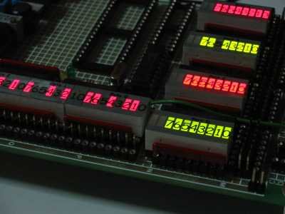
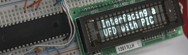 In this post I’ll show you how you can use this type of display with microcontroller. You can purchase them on Ebay as I did here.CU16025 VFD module was used for this purpose as a direct replacement for 2×16 LCD display. Although the manufacturer of these modules provides some code examples I’ve used my own driver code (originally written for a LCD) and a parallel 8 bit connection to interface this display with PIC16F877A microcontroller. I’ve adapted assembly language subroutine that I wrote earlier for VFD module initialization and for sending data/command. The code was written in C in MPLAB X using XC8 compiler. The same subroutine was also used in VFD Voltmeter project. As you can see from the schematic below 2 PORTs were used to control the display. PORTD for data/command and PORTE for RS and Enable lines.
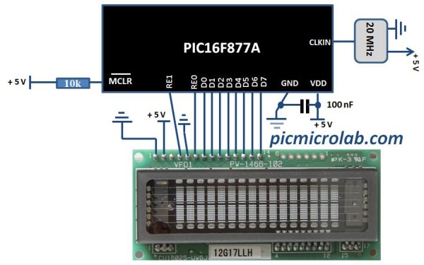


 Note : Calculation of the I²C clock value is carried out by the compiler, as it would produce a relatively large code if performed on the library level. Therefore, compiler needs to know the value of the parameter in the compile time. That is why this parameter needs to be a constant, and not a variable.