In this article you will learn how to interface temperature sensor DS18S20 with PIC16F877A microcontroller and atmega88 avr microcontroller. Complete interfacing circuit diagram and code for both PIC microcntroller and AVR microcontroller. DS18S20 interfacing with pic code is written using Mikro C for pic. Code for AVR microcontroller is written using Mikro basic complier for avr. Let’s start with basic introduction of DS18S20 digital thermometer.
DS18S20 digital thermometer
DS18S20 is 9- bit digital thermometer which is used to measure celsius tempertaure. DS18S20 also have fuction of alaram with non-volatile user programmed points. It communicates with microcontrollers with only one wire. So it works with one wire communication protocol. It requires only one data line for communication. It can also be powered from data line. It remove the need of external power supply. Each DS18S20 have unique 32 bit address. Therefore it is easy to interface multiple DS18S20’s with microcontroller.
DS18S20 applications
It have many applications. Some major applications are given below.
- industrial temperature controller
- buildings temperature controller
- digital thermometers
DS18S20 features
It have following major features as compared to other digital thermometers:
- one wire interfacing with microcontroller i.e. only one wire is required for data
- alarm setting if temperature is outside permissible limits
- Multiple devices can be interfaced with same microcotroller due to unique 64 bit address
- Maximum accuracy
- It can read temperature from -55°C to +125°C
- No need of external components. It is ready to use by interfacing with microcontroller
DS18S20 pin configuration
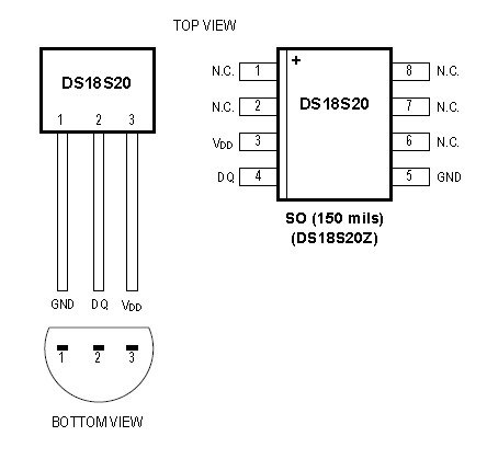
It is available in 3 pin TO-92 package and 8 pin SO package
We are using 3 pin ds18s20 package in this tutorial. Brief description of all the pins is given below:
- Number 1 : ground pin
- number 2: Data input and output pin. It is open drain one wire interfaced pin. It is also used for powered DS18S20.
- number 3: 5 volt power supply if not used in parasite power mode. if parasite power mode is used, it must be grounded
![DS18S20 interfacing with pic and avr microcontroller schematich]()
DS18s20 interfacing with PIC16F877A microcontroller
Circuit diagram for interfacing of DS18S20 is shown below. It is not used in parasite power mode. Therefore 5 volt power is connected externally. DS18S20 is interfaced with pin zero of port D. PORT D pin zero is used for one wire communication with digital thermometer. 16 ×2 LCD is used to display temperature. LCD interfacing with pic microcontroller is used to display temperature.
DS18S20 interfacing with pic code
Code for this project is written using Mikro C pro for pic.
For more detail: DS18S20 interfacing with pic and avr microcontroller
The post DS18S20 interfacing with pic and avr microcontroller appeared first on PIC Microcontroller.