Introduction
This project will describe how to make a simple digital voltmeter (DVM) using a PIC16F688 microcontroller. The range of this DVM is 0-20V, but you can easily increase or decrease the range of input voltage as your requirements after you understand the voltage scaling method described in this project. The PIC micro reads the input voltage through one of the 8 analog channels and convert it to a 10-bit digital number using the internal ADC. Doing some math with ADC conversion (you will see later), this number can be converted to the actual measured voltage. The voltage is displayed in an HD44780-based character LCD.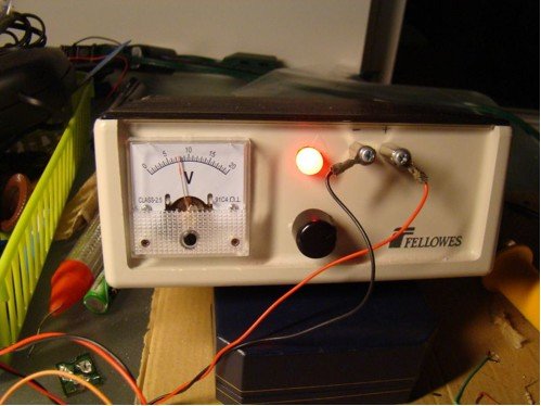
Circuit Diagram and Description
You cannot feed a 20V signal directly to a PIC microcontroller’s input channel. It is too higher than its operating voltage, and the microcontroller could be damaged. So, first we need a voltage scaler that will scale down the input voltage to the safe operating voltage range of PIC16F688. It can be achieved by a simple resistor divider network shown below.
The LCD display is connected in 4-bit mode. If you have just 14 pins in your LCD module, then you may not have a back-light facility and you can ignore the pins 15 and 16. The contrast adjustment is done through a 5K potentiometer connected between +5V and Gnd. An in-circuit serial programming (ICSP) header is provided so that you can easily upgrade the firmware inside the PIC microcontroller in future if you make any changes. An external reset is helpful to bring the entire system to a known initial condition, when the microcontroller stops executing the program for some reason.
The complete circuit built on a breadboard is shown here. You need a regulated +5V power supply for this project (Why regulated? You will find the answer in the Software section below).
Software
Before writing the code for this project, you need to do some math related to AD conversion. You know that any application that uses analog-to-digital converters (ADCs), requires a fixed reference voltage to provide accurate digital count for input analog signal. If the reference voltage is not stable, the ADC output is meaningless. In this project, the reference voltage for ADC operation is selected to be Vdd (= +5 V). This is done by clearing the VCFG bit in ADCON0 register. Therefore, the ADC will convert any input voltage between 0-5 V in to a digital count between 0-1023. A major source of error in this project is the accuracy of R1 and R2 resistors. You are recommended not to use the rated values of the resistors. Rather measure their values with a good quality digital multimeter, and use those values for your calculation. What I found is R1 = 1267 ? and R2 = 3890 ?. Now,
0 – 5 V Analog I/P is mapped to one of the 1024 levels (0-1023 Digital Count)
=> Resolution = 5/1024 = 0.0049 V/Count
To avoid floating point, use I/P voltage = 2*Digital Count. Here’s how it works. Suppose, Vin = 4.6V. Then,
In the 4-digit product (0462), the first two digits are the tens and units digits of measured voltage. and the last two are the decimal digits. So, the measured voltage will be 04.62 V. Only the first three digits will be displayed (04.6 V).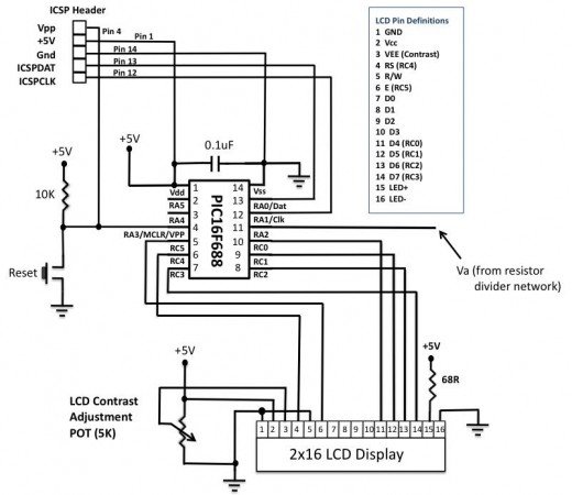
Oscillator -> Internal RC No Clock
Watchdog Timer -> Off
Power Up Timer -> On
Master Clear Enable -> Enabled
Code Protect -> Off
Data EE Read Protect -> Off
For more detail: PIC-based Digital Voltmeter (DVM)
The post PIC-based Digital Voltmeter (DVM) appeared first on PIC Microcontroller.